
Rotatable 3D printer

A 3D printer and rotary technology, applied in the direction of 3D object support structure, additive manufacturing, processing drive device, etc., can solve the problems of narrow operating space and inflexibility of nozzles, and achieve large operating space, large operating range and simple structure. Effect

Inactive Publication Date: 2018-07-24
CHENGDU YUYUE TECH CO LTD
View PDF0 Cites 1 Cited by
  • Summary
  • Abstract
  • Description
  • Claims
  • Application Information

AI Technical Summary

Problems solved by technology

[0003] The technical problem to be solved by the present invention is to provide a rotatable 3D printer, which solves the problem of narrow working space and insufficient flexibility of the 3D printer nozzle

Method used


Image

  • Rotatable 3D printer

Examples


Embodiment Construction

[0014] Embodiments of the present invention will be further described below in conjunction with the accompanying drawings.

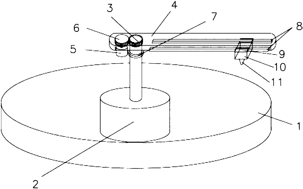
[0015] refer to figure 1 , a rotatable 3D printer described in this specific embodiment, including a workbench 1, a linear motor 2, a gear B3, a rotating arm 4, a motor 5, a gear A6, a bearing 7, a sliding rail 8, a sliding mechanism 9, and a nozzle 10 and nozzle 11, a linear motor 2 is set at the center of the workbench 1, a gear B3 is set on the top of the telescopic shaft of the linear motor 2, and the gear B3 is located in the rotating arm 4, and a motor 5 is set inside one end of the rotating arm 4, and a gear A6 is set on the rotating shaft of the motor 5. The gear A6 meshes with the gear B3, the linear motor 2 telescopic shaft is also provided with a bearing 7, the lower end of the rotating arm 4 is arranged on the bearing 7, two sliding rails 8 are arranged parallel and symmetrically on the inner side of the other end of the rotating arm 4, and t...


PUM


Abstract

The invention relates to a rotatable 3D printer. The rotatable 3D printer comprises a workable, a linear motor, a gear B, a rotating arm, a motor, a gear A, a bearing, two sliding rails, a sliding mechanism, a spray head and a nozzle, wherein the linear motor is arranged at the center of the worktable; the gear B is arranged at the top end of a telescopic shaft of the linear motor; the gear B is located in the rotating arm; the motor is arranged in one end of the rotating arm; the gear A is arranged on the rotary shaft of the motor and is engaged to the gear B; the bearing is also arranged onthe telescopic shaft of the linear motor; the lower end of the rotating arm is arranged on the bearing; the two sliding rails are symmetrically arranged on the inner side of the other end of the rotating arm in parallel; the sliding mechanism is arranged below the sliding rails; the spray head is arranged below the sliding mechanism; and the nozzle is mounted below the spray head. The rotatable 3Dprinter provided by the invention has the beneficial effects that the rotatable 3D printer is simple in structure and has a wider operational range, and the spray head is more flexible to move in a three-dimensional space.

Description

technical field [0001] The invention relates to a 3D printer, in particular to a rotatable 3D printer. Background technique [0002] At present, the nozzles of traditional 3D printers are mostly set on the moving rod, and the positioning of the nozzles of the 3D printer on the X, Y, and Z coordinates is realized by moving the rods in different directions. However, the sliding rod has a complicated mechanical structure and the positioning is not accurate and flexible enough. Shortcomings need further improvement. Contents of the invention [0003] The technical problem to be solved by the present invention is to provide a rotatable 3D printer, which solves the problem of narrow working space range and insufficient flexibility of the nozzle of the 3D printer. [0004] The technical scheme that the present invention adopts for solving the above-mentioned problem is: [0005] A rotatable 3D printer, including a worktable 1, a linear motor 2, a gear B3, a rotating arm 4, a mo...

Claims


Application Information

Patent Timeline
IPC IPC(8): B29C64/232B29C64/236B29C64/241B33Y30/00
CPCB33Y30/00
Inventor 不公告发明人
Owner CHENGDU YUYUE TECH CO LTD
Features
  • Generate Ideas
  • Intellectual Property
  • Life Sciences
  • Materials
  • Tech Scout
  • Unparalleled Data Quality
  • Higher Quality Content
  • 60% Fewer Hallucinations
Learn More