Exhausting ejection device

A technology of ejector and gas turbine, which is applied to the cooling of jet propulsion devices, gas turbine devices, and turbine/propulsion devices, etc., can solve the problems of poor engine bleed effect, gas backflow, and reduced engine test power, so as to prevent the test run. Power drop, increase rate, effect of reducing exhaust temperature

Inactive Publication Date: 2018-07-24
常州蓝森环保设备有限公司
View PDF0 Cites 8 Cited by
  • Summary
  • Abstract
  • Description
  • Claims
  • Application Information

AI Technical Summary

Problems solved by technology

[0005] The technical problem mainly solved by the present invention: aiming at the problem that the existing device has poor bleed air effect on some small and medium-sized engines with a slightly larger air flow rate, which may easily cause gas backflow and reduce the test power of the engine, the present invention provides an exhaust Ejector

Method used


Image

  • Exhausting ejection device

Examples


Embodiment Construction

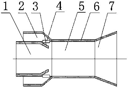
[0017] An exhaust injection device, comprising an exhaust injection tube 6, the left side of the exhaust injection tube 6 is an injection fluid channel 1, the outside of the injection fluid channel 1 is a working fluid channel 2, and the injection fluid channel 1 and working fluid channel 2 are provided with swirl flat tube 4 and windshield 3 , the right side of injection fluid channel 1 is mixing chamber 5 , and the right side of mixing chamber 5 is expansion chamber 7 . An application method of an exhaust injection device is as follows: the exhaust injection device is installed at the exhaust port of the gas turbine, the exhaust pipe of the gas turbine is connected with the injection fluid pipeline 1, and the high-speed cold air fluid enters the exhaust gas through the working fluid channel 2 Inside the gas injection tube 6, due to the high-speed flow of the working fluid, a negative pressure is generated at the junction of the injection fluid channel 1 and the working fluid ...


PUM


Abstract

The invention relates to an exhausting ejection device and belongs to the technical field of gas turbine parts. The exhausting ejection device provided by the invention is mounted at an exhausting opening of a gas turbine; an exhausting pipeline of the gas turbine is connected with an ejection fluid pipeline; high-speed cold air fluid enters an exhausting ejection barrel through a working fluid channel; working fluid flows at a high speed and negative pressure is generated at a connecting part of an ejection fluid channel and the working fluid channel; exhausted gas of the gas turbine is pumped out under the action of the negative pressure; when the working fluid passes through a cyclone flat pipe, transverse spiral is formed in a mixing room, and the exhausted gas of the gas turbine is covered with the working fluid of spiral movement and is mixed with the working fluid; finally, the exhausted gas is discharged through an expansion room. According to the exhausting ejection device provided by the invention, a wind baffle plate is arranged at the connecting part of the ejection fluid channel and the working fluid channel; the wind baffle plate can be used for increasing the flow speed of gas exhausted from the gas turbine and also can be used for preventing a condition that the exhausted gas is refluxed so that the trial output of an engine is reduced.

Description

technical field [0001] The invention relates to an exhaust injection device, which belongs to the technical field of gas turbine accessories. Background technique [0002] A typical injection mixer structure has three main components: nozzle, mixer and diffuser. The ejector mixer mixes two fluids of different pressures in the same direction to form a fluid of intermediate pressure. Among them, the high-energy and high-pressure fluid becomes the main fluid; the low-energy and low-pressure fluid is called the secondary fluid; the mixed fluid is called the mixed fluid; the ratio of the secondary flow to the main flow is called the ejection flow ratio, or Injection coefficient. From the state of the main and secondary flow, there may be the same phase of the main and secondary flow; different phases of the main and secondary flow; there is a state change (such as evaporation or condensation) in the main and secondary flow. The characteristic of the jet mixer is that it pumps ...

Claims


Application Information

Patent Timeline
Patent Type & Authority Applications(China)
IPC IPC(8): F02C3/32F02C7/18F02C7/00
CPCF02C3/32F02C7/00F02C7/18
Inventor 胡莉赵兴华蔡静
Owner 常州蓝森环保设备有限公司
Why Eureka
Try Eureka