Gas-liquid separation device and separation method for electric submersible pump

A technology of gas-liquid separation device and submersible electric pump, which is applied to pump device, components of pumping device for elastic fluid, pump, etc. problems, to achieve the effect of solving free gas content, saving energy consumption, and long maintenance-free period

Active Publication Date: 2020-01-07
PETROCHINA CO LTD
View PDF10 Cites 0 Cited by
  • Summary
  • Abstract
  • Description
  • Claims
  • Application Information

AI Technical Summary

Problems solved by technology

However, at present, the separation load range of the rotary separator is narrow, and the separation efficiency drops sharply after the maximum gas-liquid ratio is exceeded. In severe cases, air resistance occurs, and a large amount of gas is stirred and broken between the blades, resulting in uneven force on the blades and vibration of the device. Shorten stable working time and frequent maintenance
In addition, the flow of downhole liquid creates great resistance to the rotary separator, and the energy consumption increases sharply

Method used


Image

  • Gas-liquid separation device and separation method for electric submersible pump
  • Gas-liquid separation device and separation method for electric submersible pump
  • Gas-liquid separation device and separation method for electric submersible pump

Examples


Embodiment Construction

[0036] The following will clearly and completely describe the technical solutions in the embodiments of the present invention with reference to the accompanying drawings in the embodiments of the present invention. Obviously, the described embodiments are only some, not all, embodiments of the present invention. Based on the embodiments of the present invention, all other embodiments obtained by persons of ordinary skill in the art without making creative efforts belong to the protection scope of the present invention.

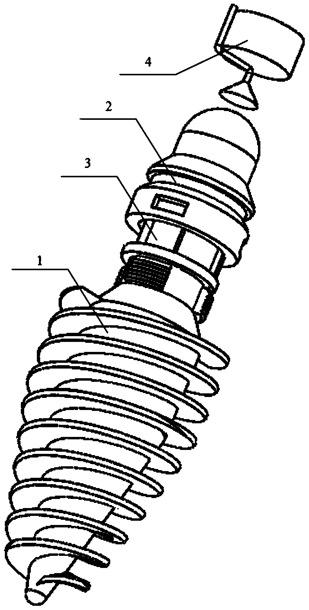
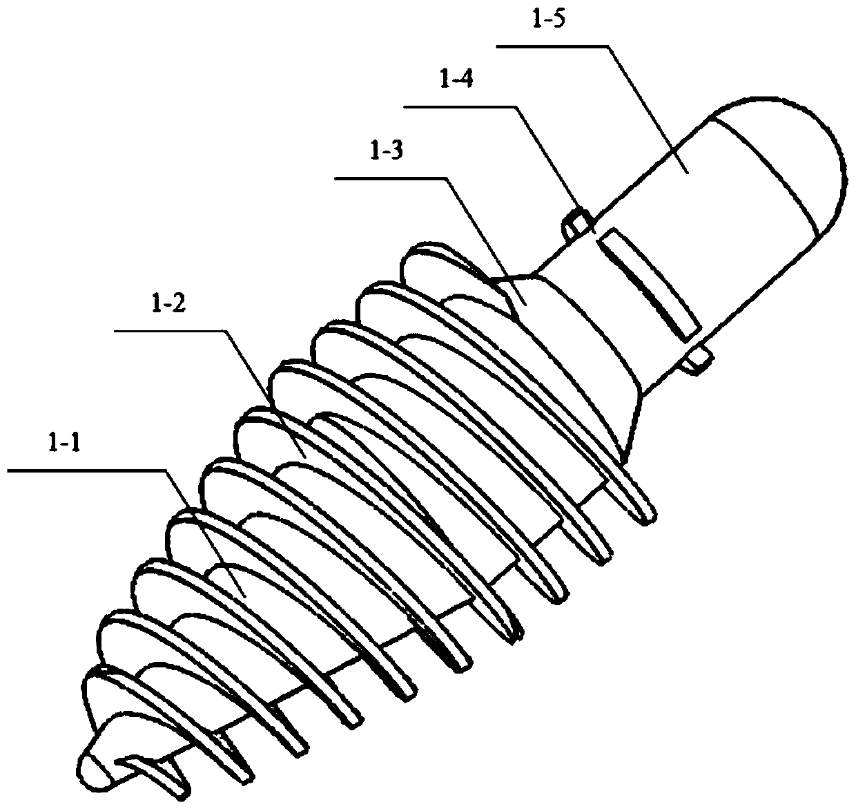
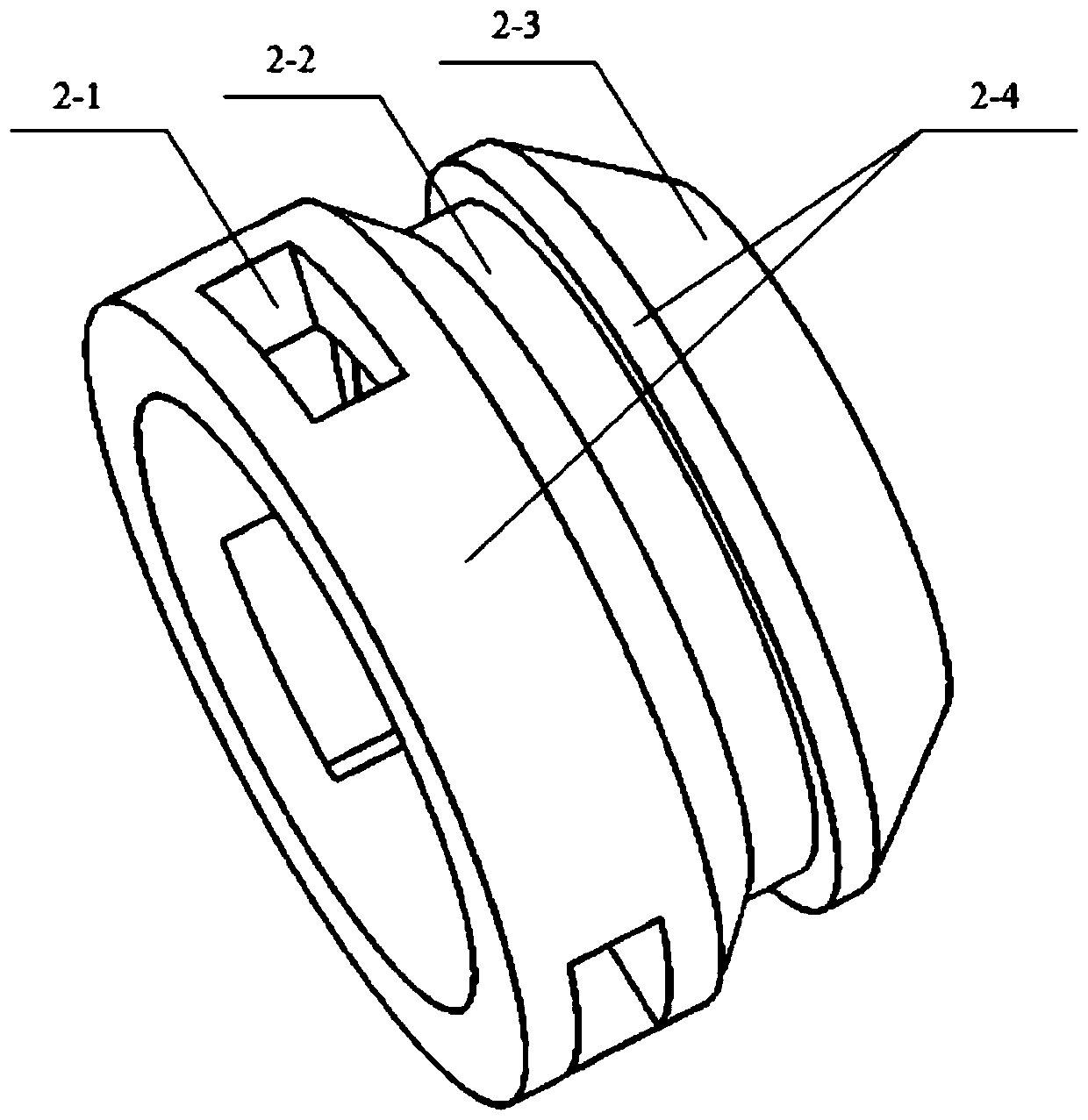
[0037] refer to figure 1 , figure 2 , image 3 , Figure 4 and Figure 5 As shown, the embodiment of the present application discloses a gas-liquid separation device for electric submersible pumps, including a separator body 1 , slips 3 , a fishing mechanism 2 and a gas collection mechanism 4 . The separator main body 1 includes a mandrel 1-5, a cone seat 1-3, and a central pipe 1-1 from top to bottom. The central pipe 1-1 is also provided with blades 1-2...


PUM


Abstract

The invention discloses a gas-liquid separation device and a separation method for a submersible electric pump, wherein the gas-liquid separation device comprises a separator main body, a slip, a fishing mechanism and a gas collecting mechanism, wherein the separator main body comprises a mandrel, a conical seat and a central pipe from top to bottom. The central tube is further provided with blades, a spiral channel extending spirally in the vertical direction is formed between the blades and the outer wall surface of the central tube, and the central tube is provided with a constant diameterportion and a gradual contractile portion connected with the lower end of the constant diameter portion. The cross-sectional area of the constant diameter portion is constant, and the cross-sectionalarea of the gradual contractile portion gradually decreases from top to bottom. The slip can fit with the conical seat, the mandrel is sleeved with the fishing mechanism, and a diversion channel whichis in communication with the spiral channel is arranged between the fishing mechanism and the mandrel. A collecting opening of the gas collecting mechanism is adjacent to the upper portion of the mandrel, and is isolated from an inlet of the submersible electric pump. The gas-liquid separation device and the separation method for the submersible electric pump have better performance.

Description

technical field [0001] The invention relates to the field of oil well gas-liquid separation, in particular to a gas-liquid separation device and a separation method for a submersible electric pump. Background technique [0002] Electric submersible pumps have the characteristics of large displacement, high head, and high degree of automation, and have been widely used in oil fields at home and abroad. When the electric submersible pump pumps gas-liquid mixed fluid, the gas entering the pump will occupy a certain space of the centrifugal pump, which will cause the characteristic curve of the submersible electric pump to deviate, the head, displacement and efficiency of the pump will decrease, and the current fluctuation will intensify when the motor is running. The production is not stable, and when it is serious, it will cause air lock, cavitation and other phenomena, and its lifting effect will be seriously affected. [0003] At present, the oil production system of electr...

Claims


Application Information

Patent Timeline
Patent Type & Authority Patents(China)
IPC IPC(8): F04D13/10F04D29/00E21B43/38E21B43/00
CPCE21B43/128E21B43/38F04D13/10F04D29/007
Inventor 邹洪岚刘永辉王青华王东平杨军征刘重伯齐丹
Owner PETROCHINA CO LTD
Why Eureka
Try Eureka