Reaction curve generation method and device and optical detection system

A reaction curve and curve technology, applied in the detection field, can solve the problems of large deviation of the reaction curve and wrong calculation results, etc., and achieve the effect of accurate absorbance value

Active Publication Date: 2018-07-24
MACCURA MEDICAL INSTR CO LTD
View PDF5 Cites 9 Cited by
  • Summary
  • Abstract
  • Description
  • Claims
  • Application Information

AI Technical Summary

Problems solved by technology

[0004] However, due to the influence of the reactant itself and other factors, agglomerated substances may be formed in the cuvette, and the agglomerated substances are easy to move randomly in the cuvette. When they block the path of the transmitted light, the collected reaction curve will appear downward. Concave V-s...

Method used


Image

  • Reaction curve generation method and device and optical detection system
  • Reaction curve generation method and device and optical detection system
  • Reaction curve generation method and device and optical detection system

Examples


Embodiment Construction

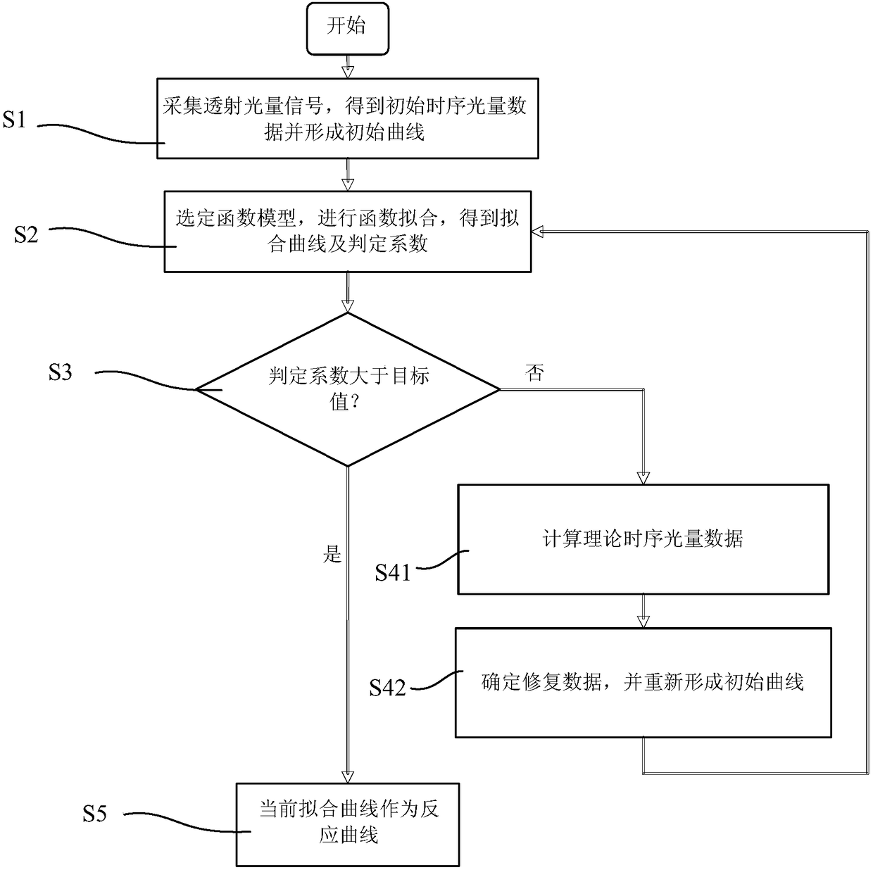
[0045] The reaction curve generation method disclosed in the present invention can be applied in the field of medical detection or chemical detection.

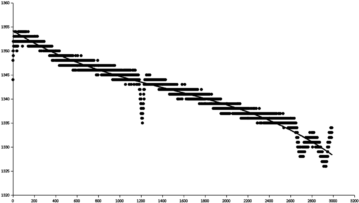
[0046] Taking the field of medical testing as an example, in fact, prior to the implementation of the present invention, those skilled in the art have tried to repair the response curves of DD and FDP in blood coagulation items showing V-shaped fluctuations. The more general repair method is to Data points with large fluctuations are removed. However, through practice verification, the inventor finds that the curve fitted by the method of removing data points has a large deviation value, and the test results are not accurate enough.

[0047] The method for generating the reaction curve in this example is mainly applicable to the turbidimetric method, and the technical solution of the present invention will be described in detail below in conjunction with specific embodiments and accompanying drawings.

[0048] A specific appli...


PUM


Abstract

The invention relates to a reaction curve generation method. The reaction curve generation method comprises the following steps: 1) acquiring a transmission light signal value to obtain initial time sequence light quantity data and form an initial curve; 2) selecting a function model meeting the initial curve and fitting according to the initial curve to obtain a fitting curve; 3) comparing whether a determination coefficient of the fitting curve is no less than a target value or not; if so, entering step 5); otherwise, entering step 4); 4) calculating theoretical time sequence light quantitydata and determining repairing data; reforming an initial curve and returning back to step 2); 5) taking the fitting curve as a reaction curve. The reaction curve formed by the method disclosed by theinvention similarly restores a reaction process at maximum so that an absorbance value calculated by the reaction curve is more accurate. The invention also relates to a reaction curve generation device and an optical detection system.

Description

technical field [0001] The invention relates to the technical field of detection, in particular to a reaction curve generation method, device and optical detection system used in the medical or chemical industry. Background technique [0002] Taking the field of medical testing as an example, DD and FDP in blood coagulation items are usually detected by turbidimetry. [0003] The principle of the turbidimetric method is: the transmitted light generated by the light source and the optical fiber is emitted from one end to the transparent cuvette, and the other end of the cuvette uses a photocell to receive the transmitted light and convert it into a signal value. When the reaction continues, the turbidity of the material in the cuvette will increase, so as the reaction time prolongs, the intensity of the transmitted light and the converted signal value will gradually decrease. Through continuous detection for a period of time, a continuous decline can be obtained. By fitting ...

Claims


Application Information

Patent Timeline
IPC IPC(8): G01N21/31
CPCG01N21/31
Inventor 吴小虎
Owner MACCURA MEDICAL INSTR CO LTD
Why Eureka
Try Eureka