Optical microscopic imaging method and device

A technology of optical microscopy and imaging devices, applied in the direction of optics, microscopes, optical components, etc., to achieve the effect of facilitating miniaturization and integration, reducing interference, and improving signal-to-noise ratio

Active Publication Date: 2018-07-24
HUAZHONG UNIV OF SCI & TECH
View PDF3 Cites 4 Cited by
  • Summary
  • Abstract
  • Description
  • Claims
  • Application Information

AI Technical Summary

Problems solved by technology

[0007] Aiming at the problems existing in the existing microscope imaging method, the first purpose of the present invention is to provide an optic

Method used


Image

  • Optical microscopic imaging method and device
  • Optical microscopic imaging method and device
  • Optical microscopic imaging method and device

Examples


Embodiment Construction

[0039] In order to make the object, technical solution and advantages of the present invention clearer, the present invention will be further described in detail below in conjunction with the accompanying drawings and embodiments. It should be understood that the specific embodiments described here are only used to explain the present invention, not to limit the present invention. In addition, the technical features involved in the various embodiments of the present invention described below can be combined with each other as long as they do not constitute a conflict with each other.

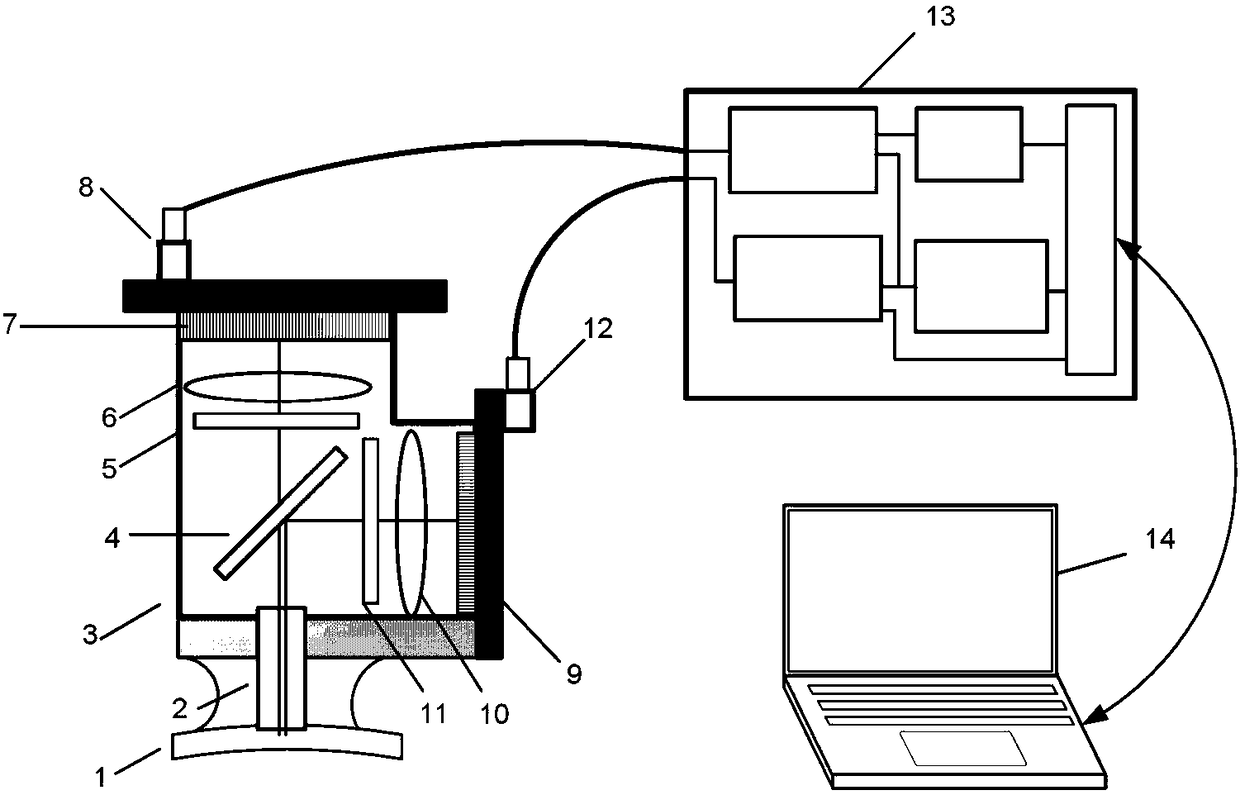
[0040] figure 1 It is a structural schematic diagram of a preferred optical microscopic imaging device of the present invention. The microscope is fixed on the sample 1, and the region of interest of the sample is imaged through an objective lens placed on the surface of the sample or inserted below the surface of the sample. The image displayed on the small display screen 9 passes through the...


PUM


Abstract

The invention discloses an optical microscopic imaging method and device, and belongs to the field of optical microscopic imaging. The optical microscopic imaging method specifically comprises the steps that a display screen sequentially displays a strip image sequence; sequentially displayed strip images form a moving illumination strip on a sample surface through an objective lens; a sample areailluminated or excited by the moving illumination strip is imaged to a detector through the objective lens; and image sequences obtained by imaging are superimposed to obtain complete image of the sample. The optical microscopic imaging device comprises a small display screen, a lens, a filter, a splitter, an objective lens and a surface array detector. In the imaging process, the width of an illumination area and the width of a detection area are simultaneously limited, the illumination process and the detection process are synchronized, a line scanning and confocal imaging mode is formed, and the restraining ability of small microscope imaging for out-of-focus signals is improved; and the small display screen is utilized, thereby not requiring the application of a mechanical scanning element, being convenient for the miniaturization and integration of a microscope system, and being applicable to performing living body in-situ microscopic imaging on the biological process.

Description

technical field [0001] The invention relates to the field of micro-optical imaging, in particular to an optical micro-imaging method and device, especially suitable for in-situ micro-imaging of biological processes. Background technique [0002] Traditionally, microscopic imaging observation of biological processes in situ requires anesthesia and fixation of experimental animals. However, for a research field such as neuroscience, the anesthesia of experimental animals will obviously limit the research that can be carried out, and may affect the experimental results, instead of reflecting the real process of neural activity. In order to be able to carry out simultaneous microscopic imaging that combines cognitive and behavioral experiments, researchers have proposed a variety of microscopic imaging techniques for conscious or even freely moving experimental animals. [0003] The overall size of the optical path and detection structure of traditional microscopes is usually m...

Claims


Application Information

Patent Timeline
IPC IPC(8): G02B21/00G02B21/06G02B21/36
CPCG02B21/0032G02B21/0052G02B21/008G02B21/06G02B21/36
Inventor 吕晓华曾绍群杨雄胡庆磊
Owner HUAZHONG UNIV OF SCI & TECH
Why Eureka
Try Eureka