Arc extinguishing system and arc extinguishing chamber

An arc extinguishing chamber and arc extinguishing technology, which is applied to electrical components, electric switches, circuits, etc., can solve problems such as failure of the arc extinguishing chamber, loss of arc extinguishing, and short circuit of the arc extinguishing grid, so as to improve the ability to withstand arc burnout , improve electrical life, reduce the effect of burning rate

Pending Publication Date: 2018-07-24
SOOAR TIANJIN ELECTRICAL EQUIP CO LTD
View PDF0 Cites 2 Cited by
  • Summary
  • Abstract
  • Description
  • Claims
  • Application Information

AI Technical Summary

Problems solved by technology

[0004] 1. The thickness of the arc extinguishing grid is not set differently according to the arc energy distribution, resulting in the arc extinguishing grid in different areas or parts having basically the same arc burning resistance, so that the arc extinguishing grid located at the lower part has been completely or Most of them are burned, but the arc extinguishing grid on the upper part is still basically intact, resulting in the failure of the entire

Method used


Image

  • Arc extinguishing system and arc extinguishing chamber
  • Arc extinguishing system and arc extinguishing chamber
  • Arc extinguishing system and arc extinguishing chamber

Examples


Example Embodiment

[0034] Implementation mode one

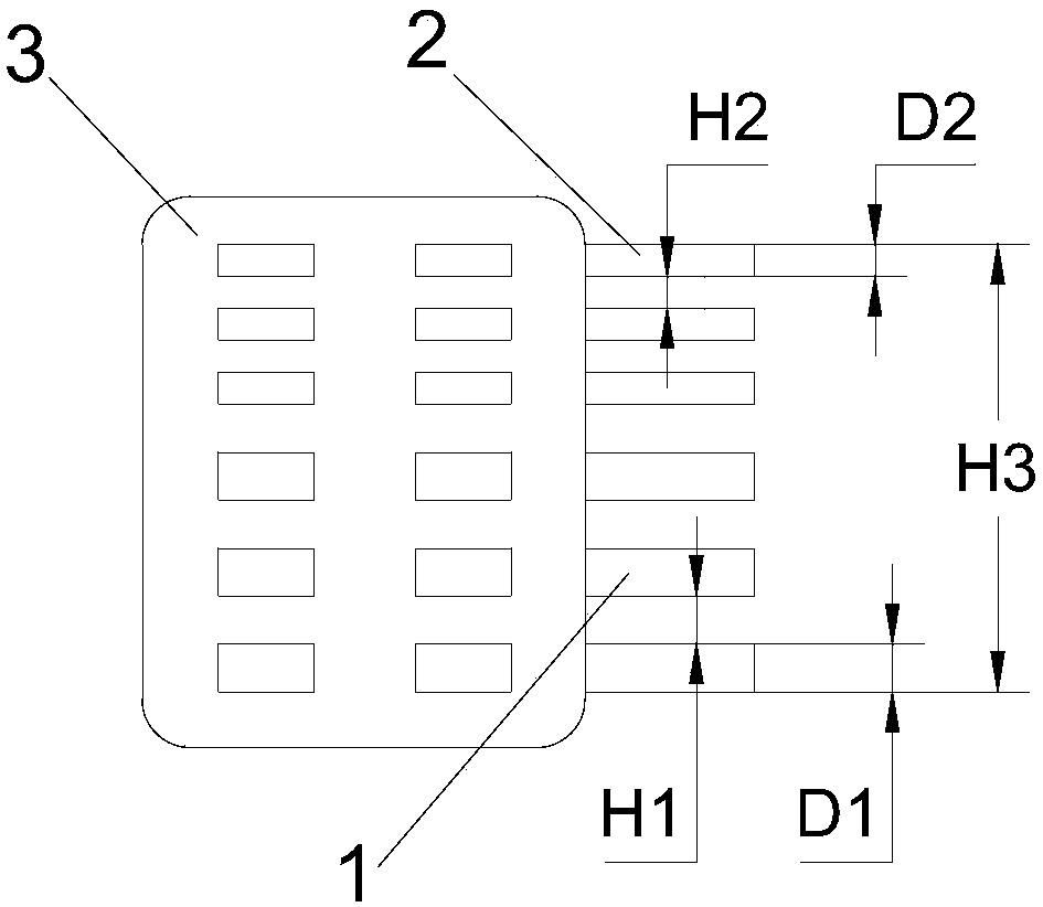
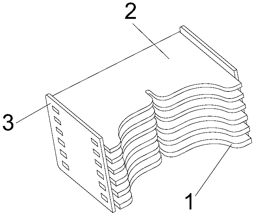
[0035] Such as Figure 1 to Figure 3 As shown, the present invention provides an arc extinguishing chamber, which includes two side plates 3 and an arc extinguishing grid set fixed between the two side plates 3, the arc extinguishing grid set includes a plurality of A first arc extinguishing grid piece 1 and a plurality of second arc extinguishing grid pieces 2, the plurality of first arc extinguishing grid pieces 1 are located below the plurality of second arc extinguishing grid pieces 2, the first arc extinguishing grid The thickness D1 of the grid piece 1 is greater than the thickness D2 of the second arc extinguishing grid piece 2, and the distance H1 between the two adjacent first arc extinguishing grid pieces 1 is larger than the two adjacent second arc extinguishing grid pieces. The distance D2 between the arc grid plates 2, where the two side plates 3 are the left and right side plates arranged vertically, and each arc extinguishing grid ...

Example Embodiment

[0048] Implementation mode two

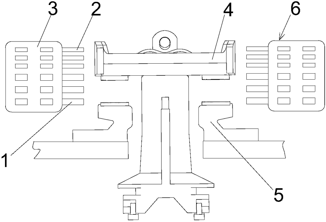
[0049] The present invention also provides an arc extinguishing system, which includes the arc extinguishing chamber 6 described in the first embodiment, and a static contact 5 and a movable contact 4 opposite to the arc extinguishing chamber 6, and the movable contact 4 can interact with The static contact 5 contacts or separates, so that the arc generated during the contact or separation process of the movable contact 4 and the static contact 5 enters the arc extinguishing grid group in the arc extinguishing chamber 6 to be cooled and cut to realize the arc The structure and beneficial effects of the arc extinguishing chamber 6 are the same as those of the first embodiment, and will not be repeated here.

[0050] In order to more clearly illustrate the improved technical effects of the present invention relative to the prior art, specific examples are described below in detail. Among them, in the following four types of electrical life tests, the ...


PUM


Abstract

The invention provides an arc extinguishing chamber, which comprises two side plates and an arc extinguishing grid plate group fixedly arranged between the two side plates. The arc extinguishing gridplate group comprises a plurality of first arc extinguishing grid plates and a plurality of second arc extinguishing grid plates. The plurality of first arc extinguishing grid plates are arranged under the plurality of second arc extinguishing grid plates; the thickness of each first arc extinguishing grid plate is larger than that of each second arc extinguishing grid plate; and the space betweentwo adjacent first arc extinguishing grid plates is larger than the space between two adjacent second arc extinguishing grid plates. The invention also provides an arc extinguishing system, which comprises the arc extinguishing chamber and a static contact and a moving contact opposite to the arc extinguishing chamber. The moving contact can be contacted with or separated from the static contact.By carrying out differentiated setting on the thickness of each arc extinguishing grid plate of the arc extinguishing grid plate group and the space between two adjacent arc extinguishing grid plates, arc erosion resistance is improved, and electrical life is improved.

Description

technical field [0001] The invention relates to the technical field of low-voltage electrical appliances, in particular to an arc extinguishing system and an arc extinguishing chamber, and more specifically to an arc extinguishing system and an arc extinguishing chamber capable of improving the electrical life and the ability of grids to resist arc burning. Background technique [0002] The air arc at atmospheric pressure is the most common form of arc in low voltage switchgear. When closing and opening most of the relays, contactors, load switches and circuit breakers that use air as the arc-extinguishing medium, air arcs under atmospheric pressure will occur. The main existing arc extinguishing method is to extinguish the arc through the arc extinguishing grid. During the breaking process of the low-voltage switching device, the arc starts to move after experiencing the arc stagnation process, and the arc is transferred from the contact to the arc track and enters the arc...

Claims


Application Information

Patent Timeline
IPC IPC(8): H01H9/36
CPCH01H9/36
Inventor 张明亮汪从礼梅梦龙
Owner SOOAR TIANJIN ELECTRICAL EQUIP CO LTD
Why Eureka
Try Eureka