Breaking-force-limiting overhead leading-in optical cable
A technology that introduces optical cables and breaking force, applied in the field of communication, can solve the problems of small overall size of optical cables, thick outer diameter of optical cables, and inconvenient construction, and achieve the effects of convenient and fast construction, reduced burning rate, and simple structure
- Summary
- Abstract
- Description
- Claims
- Application Information
AI Technical Summary
Problems solved by technology
Method used
Image
Examples
Embodiment 1
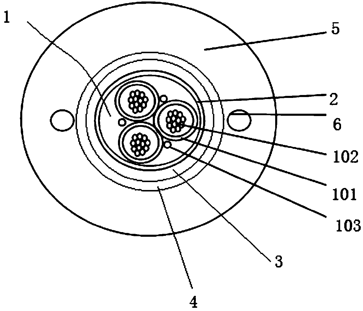
[0027] An embodiment of a limited breaking force overhead drop cable of the present invention, such as figure 1 As shown, it includes a light unit 1, the outer periphery of the light unit 1 is covered with a water blocking belt 2, the outer periphery of the water blocking belt 2 is covered with a fire-resistant film 3, and the outer periphery of the fire-resistant film 3 is covered with a fire-resistant layer 4, The outer periphery of the refractory layer 4 is covered with a PE outer sheath 5 .
[0028] In this embodiment, the refractory layer is a porcelain-able polymer refractory layer.
[0029] FRP reinforcements 6 are also provided, and the FRP reinforcements 6 are arranged on both sides of the light unit 1 .
[0030] The optical unit 1 includes several optical unit tubes 101 , and several optical fibers 102 are arranged in the optical unit tubes 101 . Water-blocking yarns 103 are arranged between the light unit tubes 101 .
[0031] The outer diameter of the lead-in cab...
Embodiment 2
[0038]In this embodiment, the formula of the refractory film includes: 50 parts of epoxy resin, 35 parts of polyamide, 9.5 parts of nano-magnesium hydroxide, 0.5 parts of polysiloxane grafted carbon nanotubes, and 5 parts of organic montmorillonite; Among them, the particle size of nano-scale magnesium hydroxide is 0.1-1 μm, the length of polysiloxane-grafted carbon nanotubes is 2-20 μm; the mass fraction of montmorillonite in organic montmorillonite is 96%-98%, and the particle size It is 300-500 mesh, and the diameter-thickness ratio is 200-300.
[0039] The refractory film is prepared through the following steps: weigh the polysiloxane grafted carbon nanotubes of the formula, dissolve them in N-N dimethylformamide solution, stir for 30 minutes while ultrasonically dispersing, and obtain a uniform mixed solution , wherein the mass ratio of polysiloxane-grafted carbon nanotubes to N-N dimethylformamide solution is 1:100; then add nano-scale magnesium hydroxide to the mixed so...
Embodiment 3
[0042] In this embodiment, the formula of the refractory film includes: 57 parts of epoxy resin, 30 parts of polyamide, 8 parts of nano-sized magnesium hydroxide, 1 part of polysiloxane grafted carbon nanotubes, and 4 parts of organic montmorillonite; Among them, the particle size of nano-scale magnesium hydroxide is 0.1-1 μm, the length of polysiloxane-grafted carbon nanotubes is 2-20 μm; the mass fraction of montmorillonite in organic montmorillonite is 96%-98%, and the particle size It is 300-500 mesh, and the diameter-thickness ratio is 200-300.
[0043] The refractory film is prepared through the following steps: weigh the polysiloxane grafted carbon nanotubes of the formula, dissolve them in N-N dimethylformamide solution, stir for 50 minutes while ultrasonically dispersing, and obtain a uniform mixed solution , wherein the mass ratio of polysiloxane-grafted carbon nanotubes to N-N dimethylformamide solution is 1:100; then add nano-scale magnesium hydroxide to the mixed ...
PUM
| Property | Measurement | Unit |
|---|---|---|
| particle diameter | aaaaa | aaaaa |
| length | aaaaa | aaaaa |
| particle size | aaaaa | aaaaa |
Abstract
Description
Claims
Application Information
 - R&D
- Intellectual Property
- Life Sciences
- Materials
- Tech Scout
- Unparalleled Data Quality
- Higher Quality Content
- 60% Fewer Hallucinations
Browse by: Latest US Patents, China's latest patents, Technical Efficacy Thesaurus, Application Domain, Technology Topic, Popular Technical Reports.
© 2025 PatSnap. All rights reserved.Legal|Privacy policy|Modern Slavery Act Transparency Statement|Sitemap|About US| Contact US: help@patsnap.com


