Surface-mounting fuse and production method thereof

A surface mount and fuse technology, applied in emergency protection devices, electrical components, circuits, etc., can solve problems such as high thermal conductivity layer or uneven thickness of adhesive, unsatisfactory arc extinguishing effect, and affecting product fusing characteristics. Achieve the effects of improving arc extinguishing effect, controllable fusing characteristics, and improving arc extinguishing effect

Pending Publication Date: 2018-07-24
AEM COMPONENTS (SUZHOU) CO LTD
View PDF11 Cites 3 Cited by
  • Summary
  • Abstract
  • Description
  • Claims
  • Application Information

AI Technical Summary

Problems solved by technology

Because the structure adopts the explosion-proof layer and is sealed in the air, it is difficult to place it horizontally. At the same time, the dimensional tolerance requirements of each part of the fuse structure are relatively high, resulting in the uneven thickness of the high thermal conductivity layer or adhesive under it, and even in the curing process. A large amount of medium infiltrates into the hollow cavity and air chamber, affecting the fusing characteristics of the product
In addition, this structure is not ideal for extinguishing the arc formed after the fuse is blown, which may cause the rupture of the fuse body during overcurrent, and even damage the protected circuit and surrounding circuit components

Method used


Image

  • Surface-mounting fuse and production method thereof
  • Surface-mounting fuse and production method thereof
  • Surface-mounting fuse and production method thereof

Examples


Embodiment 1

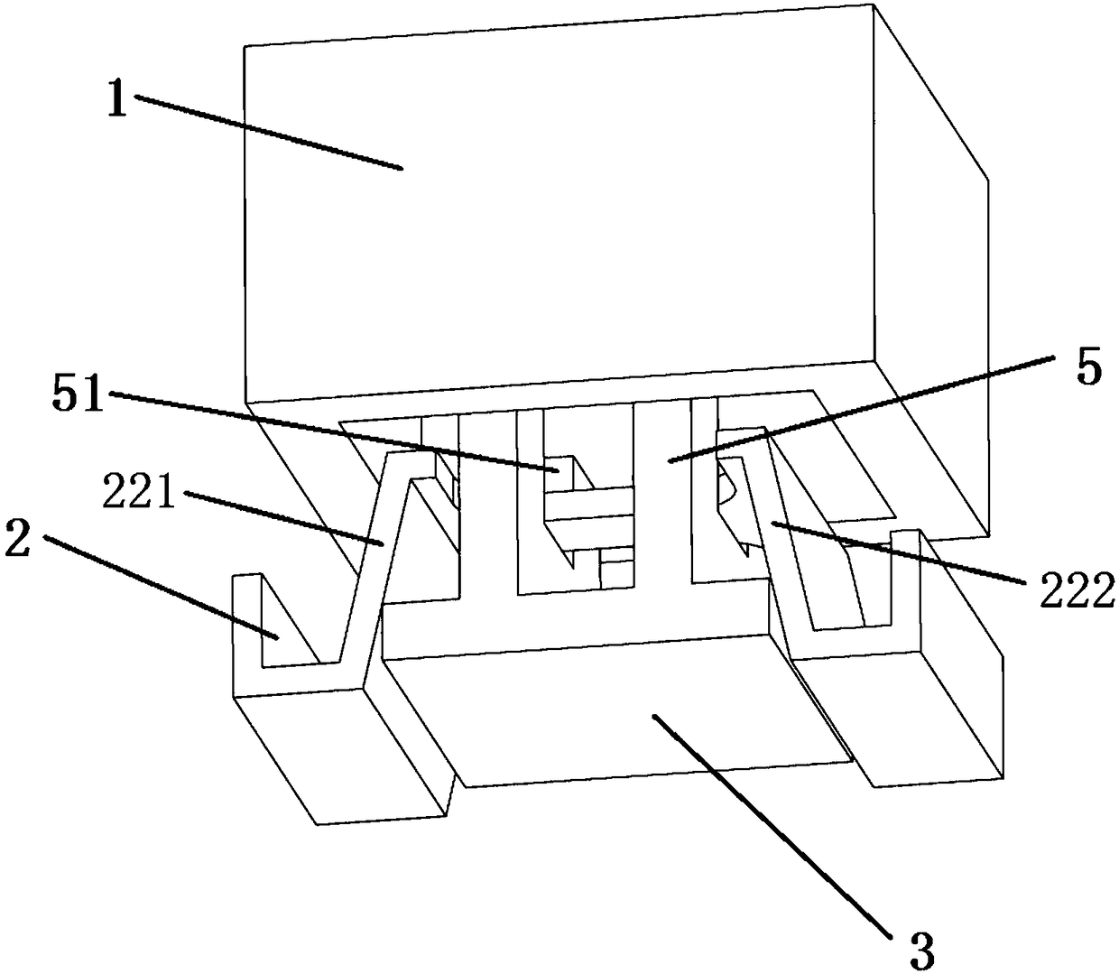
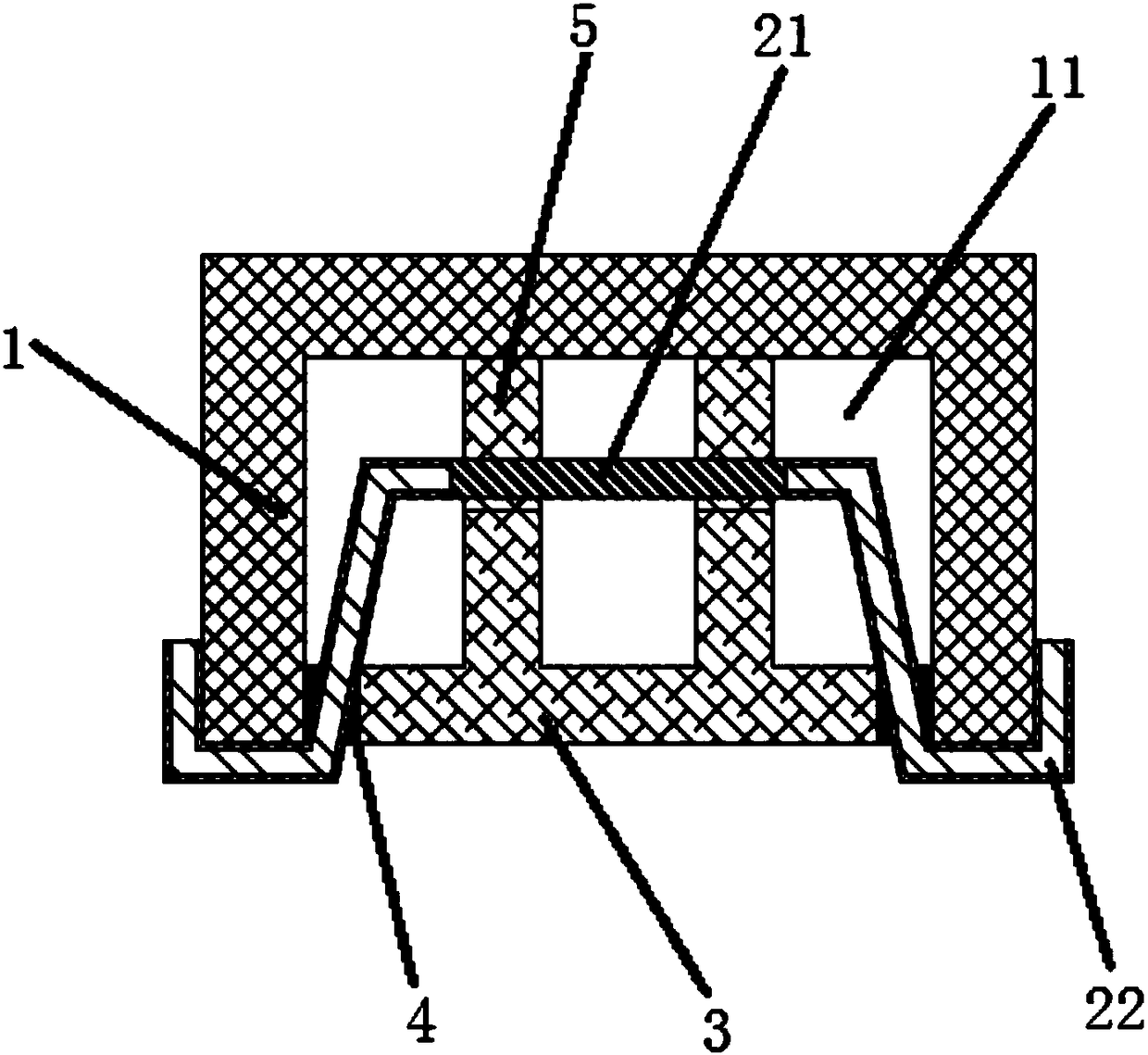
[0049] Such as Figure 1-2 As shown, this embodiment provides a surface mount fuse, which includes an insulating case 1 with an accommodating cavity 11 formed by indenting on one side, two conductive electrodes 22 and a fuse arranged between the two conductive electrodes 22. The fuse main body 2 of the part 21, the insulating cover 3 covered on the accommodating cavity 11 and the adhesive 4 filling the gap between the periphery of the insulating cover 3 and the side wall of the insulating case 1, two conductive The electrodes 22 are respectively a first conductive electrode and a second conductive electrode. There is a first bending part 221 between the first conductive electrode and the fuse part 22, and a second bend part 221 between the second conductive electrode and the fuse part 22. The bent portion 222 , the first bent portion 221 and the second bent portion 222 are located in the accommodating cavity, and the conductive electrode 22 extends out of the accommodating cav...

Embodiment 2

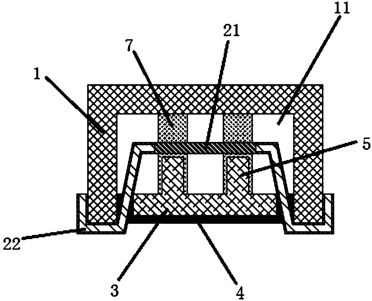
[0060] Such as image 3 As shown, this embodiment provides a surface mount fuse, which includes an insulating case 1 with an accommodating cavity 11 formed by indenting on one side, two conductive electrodes 22 and a fuse arranged between the two conductive electrodes 22. The fuse main body 2 of the part 21, the insulating cover 3 covered on the accommodating cavity 11 and the adhesive 4 filling the gap between the periphery of the insulating cover 3 and the side wall of the insulating case 1, two conductive The electrodes 22 are respectively a first conductive electrode and a second conductive electrode. There is a first bending part 221 between the first conductive electrode and the fuse part 22, and a second bend part 221 between the second conductive electrode and the fuse part 22. The bent portion 222 , the first bent portion 221 and the second bent portion 222 are located in the accommodating cavity, and the conductive electrode 22 extends out of the accommodating cavity...

Embodiment 3

[0073] Such as Figure 4 As shown, this embodiment provides a surface mount fuse, which includes an insulating case 1 with an accommodating cavity 11 formed by indenting on one side, two conductive electrodes 22 and a fuse arranged between the two conductive electrodes 22. The fuse main body 2 of the part 21, the insulating cover 3 covered on the accommodating cavity 11 and the adhesive 4 filling the gap between the periphery of the insulating cover 3 and the side wall of the insulating case 1, two conductive The electrodes 22 are respectively a first conductive electrode and a second conductive electrode. There is a first bending part 221 between the first conductive electrode and the fuse part 22, and a second bend part 221 between the second conductive electrode and the fuse part 22. The bent portion 222 , the first bent portion 221 and the second bent portion 222 are located in the accommodating cavity, and the conductive electrode 22 extends out of the accommodating cavit...


PUM


Abstract

The invention discloses a surface-mounting fuse, which comprises an insulation housing, one side of which sinks inwards to form an accommodation cavity; a fuse body having two conductive electrodes, afirst bending portion, a second bending portion and a fusing portion arranged between the two bending portions; an insulation cover body covering the accommodation cavity; and binders filling gaps between the periphery of the insulation cover body and the side walls of the insulation housing. The fusing portion and the bending portions are arranged in the accommodation cavity; the conductive electrodes extend out of the accommodation cavity; the insulation cover body is provided with support columns; and the support columns are abutted against the inner top wall of the accommodation cavity. The invention also provides a production method of the surface-mounting fuse. The surface-mounting fuse realizes pre-locating of the insulation cover body during installation; the production method issimpler; assembly difficulty is reduced; fusing performance of the product is more controllable; and meanwhile, an arc barrier is formed between the first bending portion and the second bending portion at the two ends of the fuse body, so that arc extinguishing effect is improved effectively.

Description

technical field [0001] The invention relates to the field of electrical protection components, and in particular provides a surface mount fuse and a production method thereof. Background technique [0002] Fuses are usually used as circuit protection devices and are electrically connected to the components to be protected in the circuit. A type of fuse that includes a fuse body disposed within a hollow insulating housing that melts and interrupts the circuit when a fault condition, such as an overcurrent condition, occurs in the circuit to prevent damage to the protected component or circuit. In the past, the fuse, the melt and the end cap for welding are in a separate structure. On the one hand, the structure of the fuse is more complicated and the production cost is higher. Poor contact occurs, affecting the normal operation of the circuit. [0003] Patent CN201320839953 discloses a chip fuse structure, which includes a metal sheet containing a fuse line and welding elec...

Claims


Application Information

Patent Timeline
Patent Type & Authority Applications(China)
IPC IPC(8): H01H85/175H01H85/38H01H85/18H01H69/02
CPCH01H69/02H01H85/175H01H85/18H01H85/38H01H2085/0414H01H2085/381
Inventor 刘莎胡建伟李向明杨永林
Owner AEM COMPONENTS (SUZHOU) CO LTD
Why Eureka
Try Eureka