Control method of permanent magnetism direct drive wind generator system under harmonic wave power grid voltage

A wind power generation system, permanent magnet direct drive technology, applied in the direction of motor generator control, electronic commutation motor control, wind power generation, etc., can solve the problems that affect the quality of output power of permanent magnet direct drive wind field, and the service life of DC link capacitors , to achieve the effect of improving the quality of output power, reducing operation and maintenance costs, and ensuring safe and stable operation

Active Publication Date: 2018-07-24
CHONGQING UNIV
View PDF3 Cites 6 Cited by
  • Summary
  • Abstract
  • Description
  • Claims
  • Application Information

AI Technical Summary

Problems solved by technology

[0006] Literature (2) based on the analysis of the operation behavior of the permanent magnet direct drive wind power system under the unbalanced grid voltage and harmonic distortion, proposed an improved control strategy based on the resonant sliding mode controller, which improved the traditional positive and negative control strategies to a certain extent. The delay phenomenon caused by sequence current separation reduces the design difficulty of the proportional integral controller, and effectively realizes the output current balance of the permanent magnet direct drive wind power system without distortion, but the fluctuation of the total output power and the DC bus voltage is not suppressed , affecting the output power quality of the permanent magnet direct drive wind farm and the service life of the DC link capacitor

Method used


Image

  • Control method of permanent magnetism direct drive wind generator system under harmonic wave power grid voltage
  • Control method of permanent magnetism direct drive wind generator system under harmonic wave power grid voltage
  • Control method of permanent magnetism direct drive wind generator system under harmonic wave power grid voltage

Examples


Embodiment Construction

[0038] Specific embodiments of the present invention will be described in detail below in conjunction with the accompanying drawings.

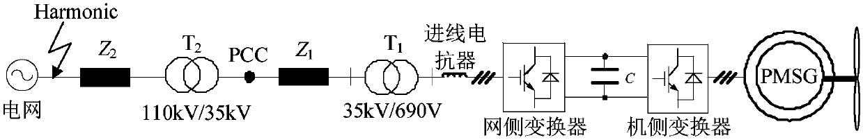
[0039] figure 1 It is a schematic diagram of the structure of the 30MVA permanent magnet direct drive wind power generation system connected to the power system. The permanent magnet direct drive wind turbine is connected to the large power grid through a public connection point.

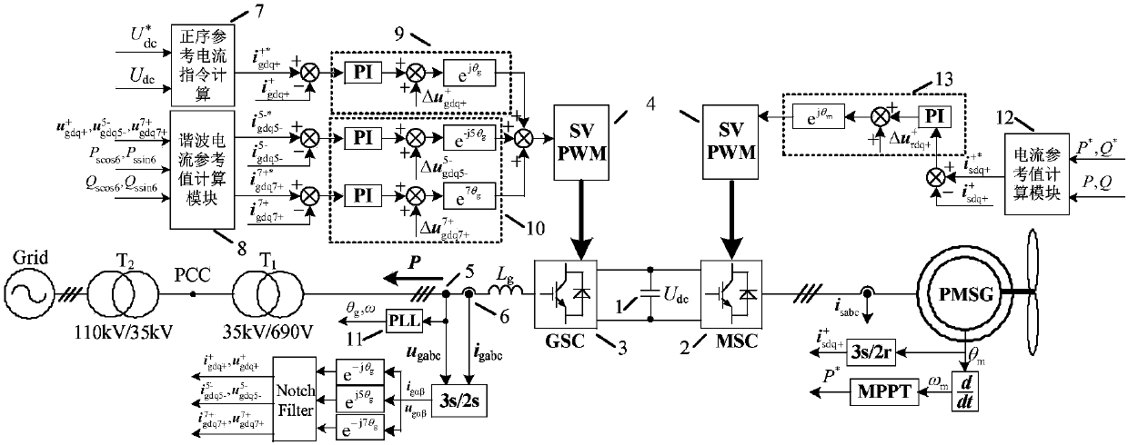
[0040] figure 2 Represents the structural block diagram of the control method of the permanent magnet direct drive wind power system under the harmonic grid voltage of the present invention, which includes the control objects: DC link capacitor 1, machine-side converter 2, grid-side converter 3, space vector modulation 4 , voltage sensor 5, current sensor 6, grid side positive sequence current reference value calculation module 7, grid side harmonic current reference value calculation module 8, grid side positive sequence current control module 9, grid side harmon...


PUM


Abstract

The invention discloses a control method of a permanent magnetism direct drive wind generator system under a harmonic wave power grid voltage; the control method relates to the control of a grid sideconverter and a machine side converter of the permanent magnetism direct drive wind generator system; the control object of the grid side converter is set to inhibit the system total output of activeand reactive power 6-frequency multiplication pulsation component; the machine side converter employs a vector control strategy, and sends a permanent magnetism direct drive wind generator system stator average active power order, and a difference between the stator average reactive power and a corresponding feedback quantity to a machine side converter current reference value calculating module,thus obtaining a current reference value; rotor field orientation is employed to send the obtained machine side converter current reference value to a machine side converter current inner ring controllink, thus obtaining a machine side converter control voltage component. The control method can improve the output electric energy quality of the permanent magnetism direct drive wind generator system, thus reducing the DC bus voltage fluctuations, improving the service life, and reducing the operation cost.

Description

technical field [0001] The invention relates to a control method for a permanent magnet direct drive wind power generation system under harmonic grid voltage, in order to reduce the harm of the harmonic grid voltage to the permanent magnet direct drive wind power system, and improve its output power quality and grid connection stability, which belongs to the new field of energy generation. Background technique [0002] In recent years, wind energy, as a green energy, has developed rapidly in the field of renewable energy. With the increasing proportion of wind power installed capacity, the impact of wind power quality on the grid has attracted more and more attention. The permanent magnet direct drive wind power system has become one of the mainstream models of wind power generation systems due to the omission of components such as brushes, slip rings, and gearboxes, and the use of full-power converters, which have high power generation efficiency and operational reliability...

Claims


Application Information

Patent Timeline
Patent Type & Authority Applications(China)
IPC IPC(8): H02J3/38H02J3/24H02P21/14H02J3/16
CPCH02J3/16H02J3/24H02J3/386H02P21/14Y02E10/76Y02E40/30
Inventor 姚骏刘瑞阔裴金鑫骆悦孙鹏
Owner CHONGQING UNIV
Why Eureka
Try Eureka