Semi-cycle three-phase T-shaped multi-level converter capacitor mid-point voltage balance control strategy

A voltage balance and converter technology, applied in the direction of converting AC power input to DC power output, electrical components, output power conversion devices, etc. tube overvoltage damage and other problems, to reduce the midpoint voltage fluctuation amplitude, improve the quality of output power, and a wide range of applications

Active Publication Date: 2016-12-07
NORTHEAST DIANLI UNIVERSITY
View PDF5 Cites 7 Cited by
  • Summary
  • Abstract
  • Description
  • Claims
  • Application Information

AI Technical Summary

Problems solved by technology

However, the three-phase T-type three-level converter has the problem of unbalanced DC capacitor midpoint voltage. Ideally, the voltages of the two capacitors are equal to 1 / 2 of the DC bus voltage. The charging and discharging are not synchronized, resulting in unequal voltages of the two capacitors, resulting in an unbalanced voltage at the midpoint of the DC capacitors, resulting in deterioration of the inverter output current waveform quality, figure 1 The voltage fluctuation waveform at the midpoint of the capacitor is
When the voltage at the midpoint of the capacitor is seriously unbalanced, it will cause the DC filter capacitor and the switch tube on the bridge arm to bear high DC voltage, reduce the working life of the capacitor and the switch tube, and eventually lead to capacitor breakdown and switch tube overvoltage damage
[0003] The existing DC capacitor voltage deviation feed-forward control strategy is generally used for the sinusoidal pulse width modulation (Sinusoidal Pulse Width Modulation, SPWM) method of the three-phase T-type three-level converter. In the case of relatively small modulation, and only for a fixed output power voltage equalization effect is good

Method used


Image

  • Semi-cycle three-phase T-shaped multi-level converter capacitor mid-point voltage balance control strategy
  • Semi-cycle three-phase T-shaped multi-level converter capacitor mid-point voltage balance control strategy
  • Semi-cycle three-phase T-shaped multi-level converter capacitor mid-point voltage balance control strategy

Examples


Embodiment Construction

[0022] The sinusoidal pulse width modulation strategy of the three-phase T-type three-level inverter of the present invention will be described in detail below in conjunction with the drawings and embodiments.

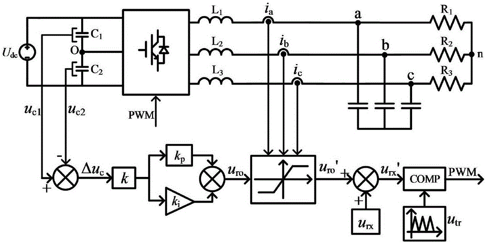
[0023] refer to figure 1 and figure 2 , the three-phase T-type three-level inverter sinusoidal pulse width modulation strategy of the present invention includes the following:

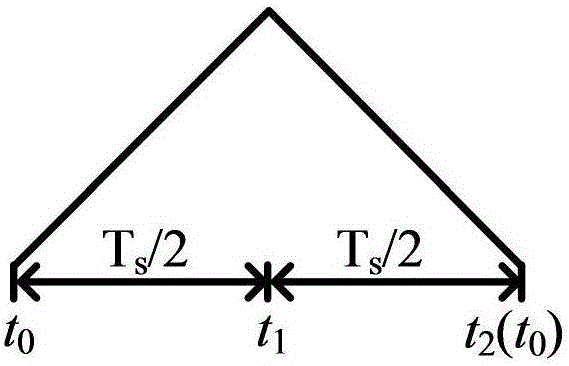
[0024] 1) When the converter adopts dual-carrier in-phase SPWM control strategy, the three-phase modulated wave u in one carrier period ra , u rb and u rc with two carriers u c1 and u c2 Comparing to obtain a total of six switch tube PWM drive signals T in each phase A1 , T A2 , T B1 , T B2 , T C1 and T C2 , to control the opening and closing of the switching tubes of each phase. Let the start time of a switching cycle be t 0 , the middle moment is t 1 , the end time is t 2 ;

[0025] 2) At each switching cycle t 0 Collect the output current of the AC side of the converter at ...


PUM


Abstract

The invention provides a semi-cycle three-phase T-shaped multi-level converter capacitor mid-point voltage balance control strategy. The strategy is characterized in that a balance control cycle is changed, one-time sampling is conducted on capacitor mid-point voltage every semi-cycle to obtain voltage difference; a gain coefficient is calculated according to the amplitude value of load current, PI operation is conducted on the voltage difference to obtain a control parameter; amplitude limiting is conducted on the control parameter according to an effective current value, further new modulating waves are obtained and are compared with carrier waves to obtain a PWM signal finally driving a switch tube. The strategy does not need to detect capacitor mid-point current and judge the working state of a bridge arm, can effectively decreased capacitor mid-point voltage fluctuation amplitude and improve the quality of electric energy output by a converter and has the advantages of being scientific, reasonable, good in applicability, wide in application range, good in effect and the like.

Description

technical field [0001] The invention relates to the field of power electronics, and relates to a half-period three-phase T-type three-level converter capacitor midpoint voltage balance control strategy. Background technique [0002] The three-phase T-type three-level converter has the advantages of small switching loss, high power conversion efficiency, low output current harmonic content and small filter inductance value, and is widely used in new energy power generation fields such as photovoltaic power generation and wind power generation. . However, the three-phase T-type three-level converter has the problem of unbalanced voltage at the midpoint of the DC capacitors. Ideally, the voltages of the two capacitors are equal to 1 / 2 of the DC bus voltage. The charging and discharging are not synchronized, resulting in unequal voltages of the two capacitors, resulting in an unbalanced voltage at the midpoint of the DC capacitors, resulting in deterioration of the inverter out...

Claims


Application Information

Patent Timeline
Patent Type & Authority Applications(China)
IPC IPC(8): H02M7/487
CPCH02M7/487
Inventor 严干贵段双明吴薇靳利光贾祺
Owner NORTHEAST DIANLI UNIVERSITY
Why Eureka
Try Eureka