ZSC-SMES topological structure and AC/DC side control method thereof
A technology of topology structure and control method, which is applied in the direction of converting AC power input to DC power output, output power conversion device, electrical components, etc., and can solve the problems of switch tube bridge arm straight-through, economic loss, dynamic response ability and poor robustness And other issues
- Summary
- Abstract
- Description
- Claims
- Application Information
AI Technical Summary
Problems solved by technology
Method used
Image
Examples
Embodiment 1
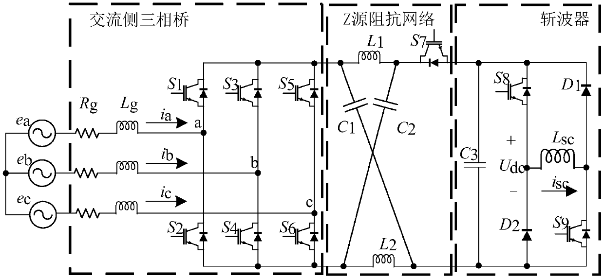
[0089] like figure 1 As shown, a kind of ZSC-SMES topological structure of the present invention, comprises the AC side three-phase bridge circuit, Z source impedance network and chopper connected in sequence, the input end of described AC side three-phase bridge circuit is connected to three-phase grid;
[0090] The Z source impedance network includes a capacitor C1, a capacitor C2, an inductor L1, an inductor L2, and a switch tube S7. One end of the inductor L1, one end of the capacitor C1, and the positive output of the three-phase bridge circuit on the AC side share a node, and the inductor L1 The other end, the drain of the switch tube S7 and one end of the capacitor C2 share a node, one end of the inductor L2, the other end of the capacitor C2 and the output negative pole of the three-phase bridge circuit on the AC side share a node, the other end of the inductor L2, and the other end of the capacitor C1 One terminal has a common node with the output negative pole of the...
Embodiment 2
[0094]In this embodiment, on the basis of Embodiment 1, the AC-side three-phase bridge circuit adopts a three-phase inverter bridge circuit. The chopper includes a switching tube S8, a switching tube S9, a capacitor C3, an inductor Lsc, a diode D1, and a diode D2; one end of the capacitor C3, the drain of the switching tube S8, and the cathode of the diode D1 have a common node and serve as a chopper The output anode of the device is connected to the Z source impedance network, the other end of the capacitor C3, the anode of the diode D2 and the source of the switch tube S9 have a common node and are connected to the Z source impedance network as the output cathode of the chopper; the switch The source of the transistor S8, the cathode of the diode D2, and one end of the inductor Lsc share a node, and the other end of the inductor Lsc, the drain of the switching transistor S9, and the anode of the diode D1 share a node.
Embodiment 3
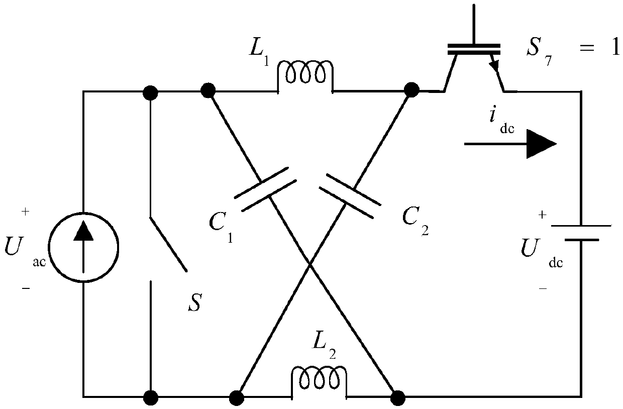
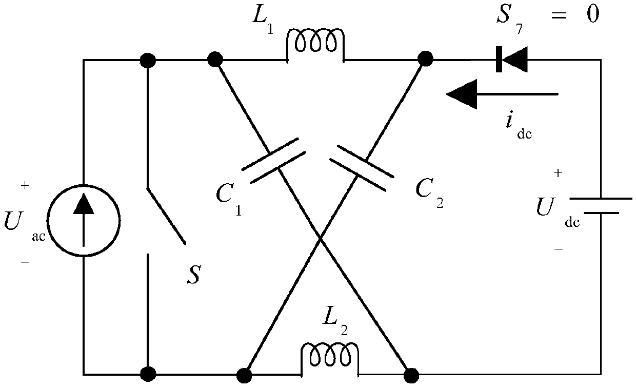
[0096] This embodiment is on the basis of embodiment 1 and embodiment 2, as figure 1 As shown, the topology of ZSC-SMES is as follows figure 1 As shown, it consists of an AC side ZSC and a DC side chopper. Among them, the ZSC is divided into two parts: the three-phase bridge on the AC side and the Z source impedance network. The bidirectional power flow on the AC and DC sides of the ZSC-SMES is controlled by the switching tube S in the Z source network. 7 state decision. In the figure, L g and R g Respectively represent the inductance value and resistance value of the grid side of the converter; L 1 , L 2 and C 1 、C 2 Respectively represent the inductance value and capacitance value in the Z source network; U dc Indicates the DC side voltage value; L sc Indicates the magnet inductance value; i sc is the magnitude of the magnet current; e a 、e b 、e c Respectively represent the three-phase sinusoidal grid voltage.
[0097] Through equal power conversion, the mathem...
PUM
 Abstract
Description
Claims
Application Information
 - R&D
- Intellectual Property
- Life Sciences
- Materials
- Tech Scout
- Unparalleled Data Quality
- Higher Quality Content
- 60% Fewer Hallucinations
Browse by: Latest US Patents, China's latest patents, Technical Efficacy Thesaurus, Application Domain, Technology Topic, Popular Technical Reports.
© 2025 PatSnap. All rights reserved.Legal|Privacy policy|Modern Slavery Act Transparency Statement|Sitemap|About US| Contact US: help@patsnap.com


