Electric bridge system

A technology of electric drive and drive motor, applied in the direction of electric power device, power device, control device, etc., can solve the problems of the maximum speed and speed ratio of the reducer, reduce the requirements, meet the requirements of the highest speed and power, Avoid the effects of NVH

Inactive Publication Date: 2018-07-27
CH AUTO TECH CORP CO LTD
View PDF6 Cites 4 Cited by
  • Summary
  • Abstract
  • Description
  • Claims
  • Application Information

AI Technical Summary

Problems solved by technology

[0004] In view of this, the present invention proposes an electric drive axle system, which aims to solve the problem that

Method used


Image

  • Electric bridge system
  • Electric bridge system
  • Electric bridge system

Examples


Embodiment Construction

[0025] Exemplary embodiments of the present disclosure will be described in more detail below with reference to the accompanying drawings. Although exemplary embodiments of the present disclosure are shown in the drawings, it should be understood that the present disclosure may be embodied in various forms and should not be limited by the embodiments set forth herein. Rather, these embodiments are provided for more thorough understanding of the present disclosure and to fully convey the scope of the present disclosure to those skilled in the art. It should be noted that, in the case of no conflict, the embodiments of the present invention and the features in the embodiments can be combined with each other. The present invention will be described in detail below with reference to the accompanying drawings and examples.

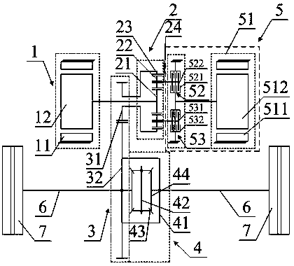
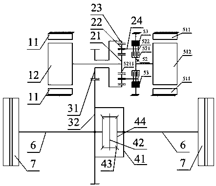
[0026] see figure 1 , which is a schematic structural diagram of the electric drive axle system provided by the embodiment of the present invention, the elec...


PUM


Abstract

The invention provides an electric bridge system, comprising: a first driving motor for driving vehicle hubs to rotate; a planet gear mechanism, wherein an input shaft of the planet gear mechanism isconnected with an output shaft of the first driving motor, and the planet gear mechanism is used for driving the hubs to rotate; a driving mechanism connected with the planet gear mechanism and used for selectively driving the planet gear mechanism to rotate so as to adjust the speed of the hubs. The first driving motor cooperates with the planet gear mechanism to transmit power; the driving mechanism selectively drives the planet gear mechanism to rotate so as to selectively increase the output speed of the planet gear mechanism; the first driving motor and the driving mechanism cooperate with the planet gear mechanism so that the output speed of the planet gear mechanism is adjusted under fixed tooth ratio to adjust vehicle speed; therefore, the requirement on highest speed of the motoris lowered.

Description

technical field [0001] The invention relates to the technical field of drive, in particular to an electric drive axle system. Background technique [0002] The drive system of new energy vehicles generally consists of an electric drive axle composed of a motor and a reducer. The motor converts electrical energy into mechanical energy to provide power for the vehicle, and then reduces the speed of the motor through the reducer, and at the same time amplifies the output torque of the motor to achieve the effect of deceleration and torque increase, so that the vehicle can run within a certain speed range and under a certain driving force . At present, the electric drive system in new energy vehicles is generally composed of a motor and a reducer with a fixed gear ratio. In order to meet the maximum speed of the vehicle, the motor speed needs to be adjusted within a wide range. The high-power motor is matched with the whole vehicle. [0003] However, the adjustment of the spe...

Claims


Application Information

Patent Timeline
IPC IPC(8): B60K1/02B60K17/02B60K17/08
CPCB60K1/02B60K17/02B60K17/08
Inventor 陆群陈峥光
Owner CH AUTO TECH CORP CO LTD
Why Eureka
Try Eureka