
Steel-concrete composite beam structure with composite bonding anchorage shear-resistant joint and production method

A production method and technology of composite beams, applied in bridges, bridge parts, bridge construction, etc., can solve problems such as low service life of bridge deck components, full bridge structural design service life, increased bridge life cycle costs, fatigue damage of concrete bridge decks, etc. , to achieve the effects of improving the stress state, reducing fatigue stress, and improving stress concentration

Pending Publication Date: 2018-07-27
HUAQIAO UNIVERSITY
View PDF8 Cites 4 Cited by
  • Summary
  • Abstract
  • Description
  • Claims
  • Application Information

AI Technical Summary

Problems solved by technology

[0003] At present, the stud shear connectors commonly used in composite beam bridge structures have local stress concentration phenomenon under load, and the studs are prone to fatigue fracture under the action of vehicle load; the concrete bridge deck is prone to fatigue failure under the action of vehicle fatigue load. The service life of the bridge deck components is lower than the design service life of the whole bridge structure, and the composite structure bridge needs to replace the concrete deck during operation, which increases the life cycle cost of the bridge

Method used


Image

  • Steel-concrete composite beam structure with composite bonding anchorage shear-resistant joint and production method
  • Steel-concrete composite beam structure with composite bonding anchorage shear-resistant joint and production method
  • Steel-concrete composite beam structure with composite bonding anchorage shear-resistant joint and production method

Examples


Embodiment Construction

[0028] The present invention will be further described in detail below in conjunction with the accompanying drawings and embodiments.

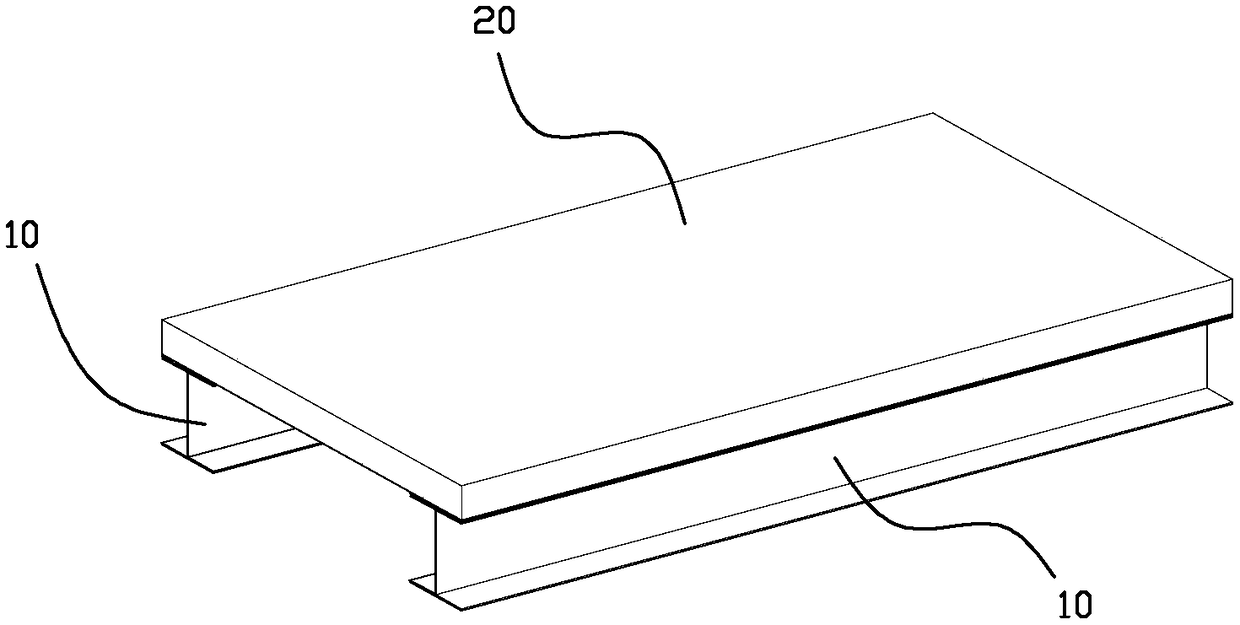
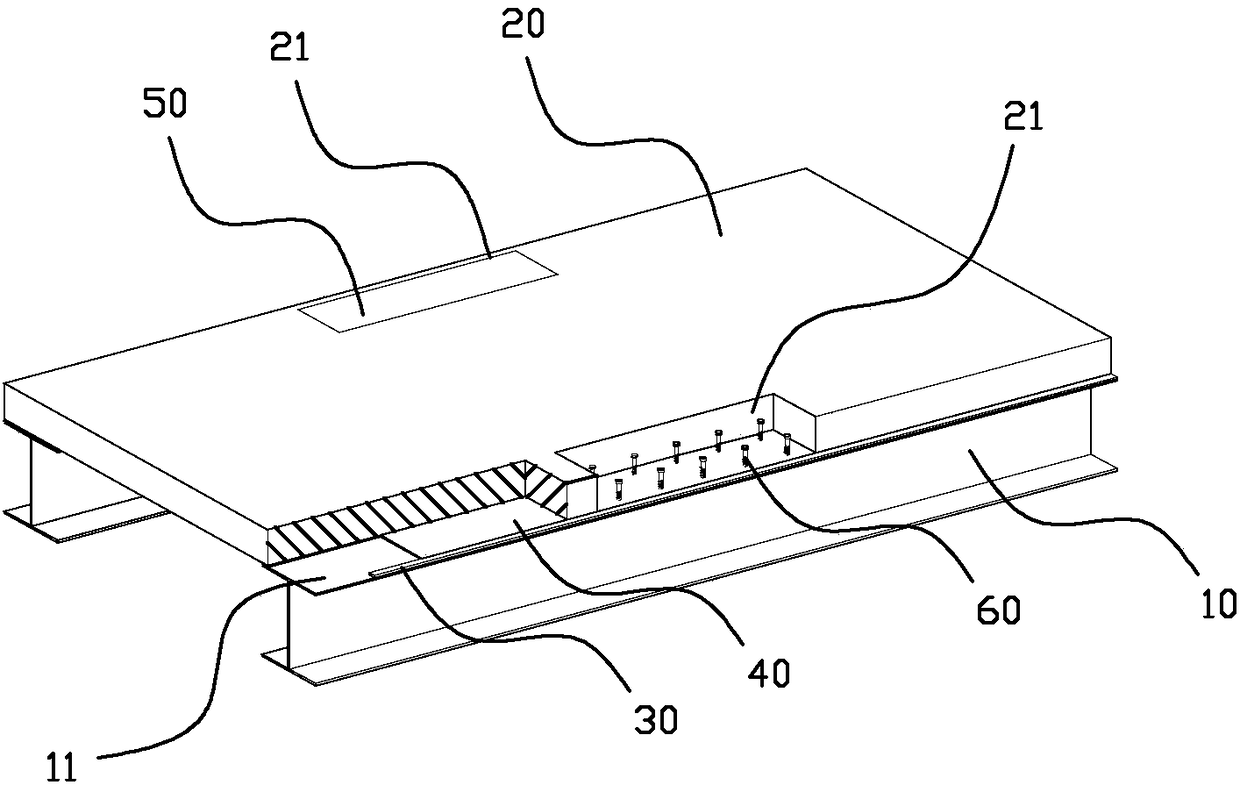
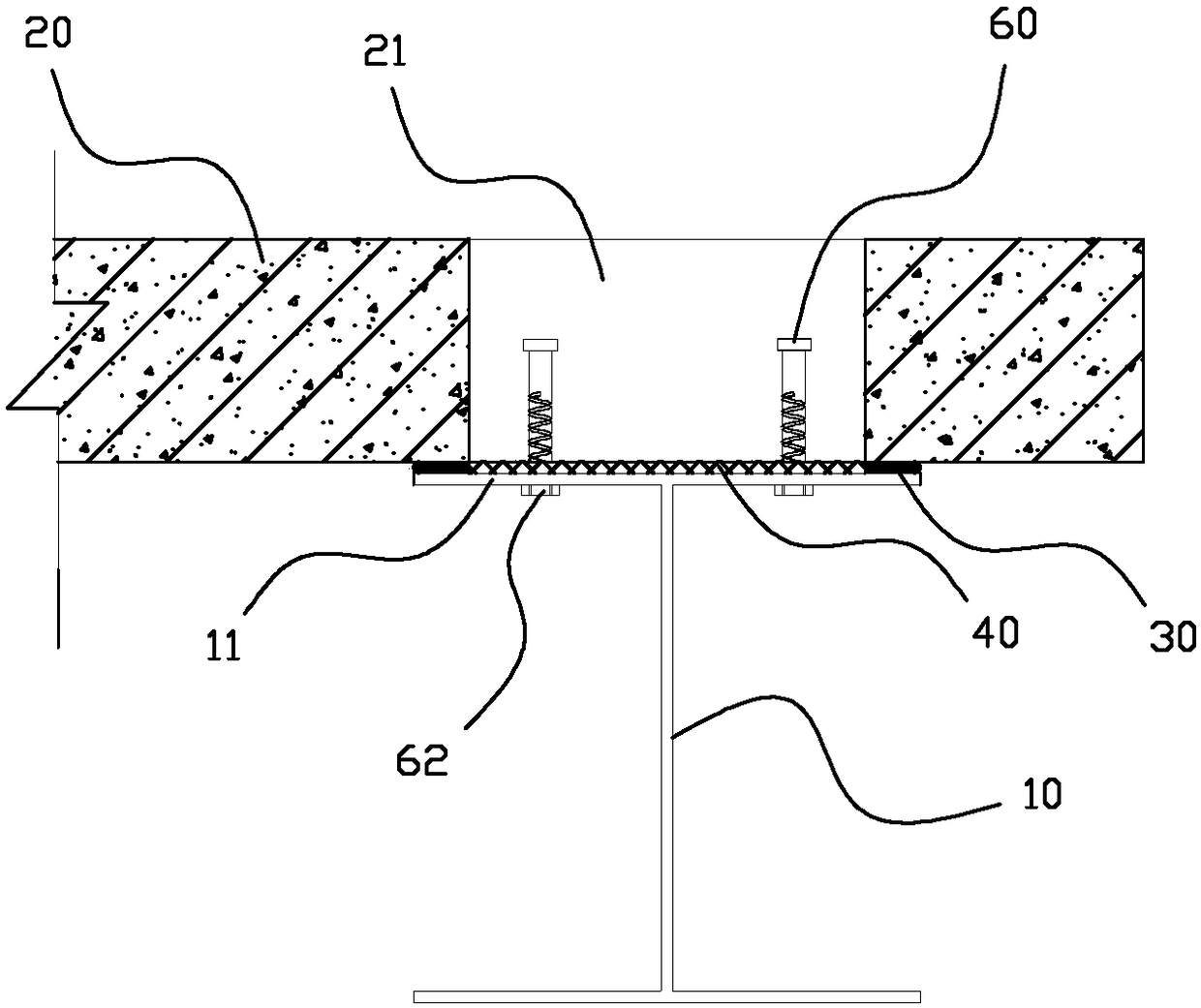
[0029] In order to solve the deficiencies in the steel-concrete composite beam bridges of the prior art, the present invention provides a steel-concrete composite beam structure with an interface preloaded composite bonded anchorage shear connection, and a production method thereof, which improves the performance of composite beam bridges. The service life of the stud connector and the concrete bridge deck is reasonable, the structure is simple, the mechanical performance is superior, and the construction is convenient.

[0030] like figure 1 , figure 2 As shown, a steel-concrete composite beam structure with interfacial precompression composite bonded anchorage shear connection, including prefabricated bridge deck 20, steel beam 10 (commonly I-beam), bridge deck 20 bonded to the steel beam The upper wing plate 11 of 10, the bottom surface ...


PUM


Abstract

The invention relates to an interface pre-compression steel-concrete composite beam structure with a composite bonding anchorage shear-resistant joint and a production method thereof. The mode that anepoxy mortar layer and a shear resistance bolt are compositely connected is adopted, pre-tightening force is applied through the shear resistance bolt, thus the bonding interface of a concrete slab and a steel beam are in a pre-compaction state, and the concrete bridge deck slab and the steel beam are connected; meanwhile, friction shear resistance of the epoxy mortar shear-resistant connecting layer and the bonding interface can improve the stress state of bolt local stress concentration; and after the pre-tightening force is applied by the shear resistance bolt, the bonding surfaces of theepoxy mortar layer and the steel beam as well as the epoxy mortar layer and the prefabricated bridge deck slab are in a pre-compression state, in the bridge operating process, part of shear force between the concrete slab and the steel beam can be transmitted through the epoxy mortar layer, fatigue stress of the shear resistance bolt is reduced, the stress concentration phenomenon of the joint ofthe concrete slab and the bolt is avoided, and the fatigue life of the beam and bridge composite structure is prolonged.

Description

technical field [0001] The invention relates to the field of civil engineering, more specifically, to a steel-concrete composite beam structure with interface preloaded composite bonded anchorage shear connection, and a steel-concrete composite beam structure with interface preloaded composite bonded anchorage shear connection Method of production of composite beam structures. Background technique [0002] In recent years, steel-concrete composite girder bridges have been more widely used in my country. This type of bridge can give full play to the performance of steel and concrete, has good seismic performance, and can reduce its own weight, increase the clearance under the bridge, and effectively Shorten the construction period. But the composite girder bridge of prior art still exists some deficiencies: [0003] At present, the stud shear connectors commonly used in composite beam bridge structures have local stress concentration phenomenon under load, and the studs are ...

Claims


Application Information

Patent Timeline
IPC IPC(8): E01D2/02E01D19/00E01D19/12E01D21/00
CPCE01D2/02E01D19/00E01D19/125E01D21/00
Inventor 林建平唐俊福霍静思周磊彭仲鑫
Owner HUAQIAO UNIVERSITY
Learn More