Medium-wave infrared searching and tracking lens based on compensating mirror

A compensating mirror and infrared technology, which is applied in the field of mid-wave infrared search and tracking lenses, can solve the problems of large compensating mirror size, low processing difficulty, and high control difficulty, so as to improve imaging quality, reduce stray light, and improve economic efficiency. Effect

Active Publication Date: 2018-07-27
XI'AN INST OF OPTICS & FINE MECHANICS - CHINESE ACAD OF SCI +1
View PDF9 Cites 0 Cited by
  • Summary
  • Abstract
  • Description
  • Claims
  • Application Information

AI Technical Summary

Problems solved by technology

figure 1 It is a common layout for the medium compensation mirror to be located in front of the infrared search and track lens. The design of the infrared search and track lens in this layout is simple, and its imaging quality is only related to the compensation mirror surface type (small-caliber high-precision surface type is less difficult to process), and its corner Irrelevant, so the image quality of the system is good, but the compensation mirror is placed in the optical path at the front of the lens at a certain angle. In order to detect a large field of view, the size of the compensation mirror is required to be large, the control is difficult, and the economy is poor.

Method used


Image

  • Medium-wave infrared searching and tracking lens based on compensating mirror
  • Medium-wave infrared searching and tracking lens based on compensating mirror
  • Medium-wave infrared searching and tracking lens based on compensating mirror

Examples


Embodiment Construction

[0037] Specific embodiments of the present invention will be further described in detail below in conjunction with the accompanying drawings.

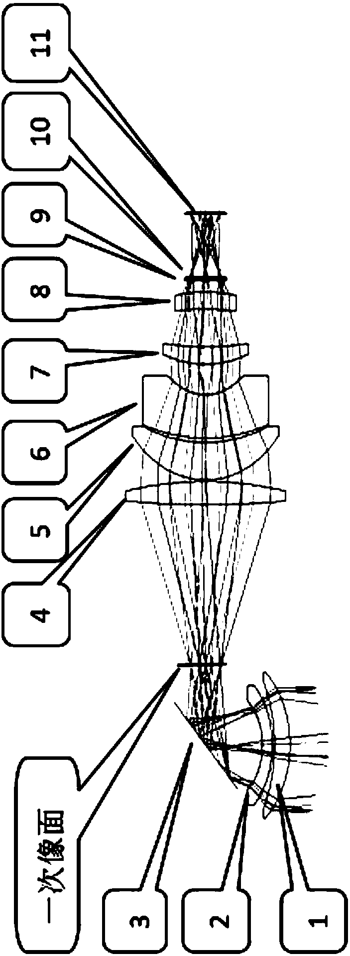
[0038] like figure 2 The shown 75mm / F2 infrared search and track lens based on compensating mirror adopts 3 groups of 8 elements, including the first objective lens, the second objective lens, the compensating mirror, the first projection objective lens, the second projection objective lens, and the third projection objective lens , the fourth projection objective lens and the fifth projection objective lens;

[0039] The optical radiation of the detection target is converged on the primary image plane by the first objective lens, the second objective lens and the compensation mirror, and then imaged by the first projection objective lens, the second projection objective lens, the third projection objective lens, the fourth projection objective lens and the fifth projection objective lens On the photosensitive surface of the external...


PUM


Abstract

The invention belongs to the field of optical devices, and particularly relates to a medium-wave infrared searching and tracking lens based on a compensating mirror. By integrating the compensating mirror in an optical system of the lens, the lens is good in imaging quality, compact in structure, low in compensating mirror control difficulty and high in economy and can meet the actual use requirements. The basic structure of the lens comprises a first objective lens, a second objective lens, the compensating mirror, a first projection objective lens, a second projection objective lens, a thirdprojection objective lens, a fourth protection objective lens and a fifth projection objective lens. Light radiation of a detection target is gathered on a primary image surface by the first objective lens, the second objective lens and the compensating mirror and then imaged on a photosensitive surface of an external thermal infrared imager by the first projection objective lens, the second projection objective lens, the third projection objective lens, the fourth protection objective lens and the fifth projection objective lens, and meanwhile the requirement for imaging an entrance pupil ona cold screen of an external self-cooled type detector is met.

Description

technical field [0001] The invention belongs to the field of optical equipment, and in particular relates to a mid-wave infrared search and tracking lens based on a compensation mirror. Background technique [0002] The infrared search and track system rotates along the azimuth at a certain speed, and through the equipped infrared search and track imaging system, it can image the surrounding azimuth 360° and within a certain distance, so as to detect suspicious targets and play an early warning role. Because there is no blind spot in the 360° azimuth imaging and the detection probability is high, it is widely used, especially in military early warning, border defense monitoring, forest fire prevention, etc. [0003] The infrared search and tracking system realizes the azimuth 360° imaging methods mainly include: line scan imaging, staring device slow scan imaging, staring device step scan imaging and reverse scan compensation imaging. Among them, the reverse scanning compen...

Claims


Application Information

Patent Timeline
Patent Type & Authority Applications(China)
IPC IPC(8): G02B13/18G02B13/14G02B13/16G02B13/00
CPCG02B13/0005G02B13/146G02B13/16G02B13/18
Inventor 李刚高昕刘波李传刚
Owner XI'AN INST OF OPTICS & FINE MECHANICS - CHINESE ACAD OF SCI
Why Eureka
Try Eureka