Open charging machine

A charging machine and an open technology, applied in the direction of current collectors, electric vehicles, electrical components, etc., can solve the problems of high energy consumption, heavy overall weight, and slow heat dissipation of trains, and achieve compact structure, meet weight reduction, and reduce volume effect with weight

Pending Publication Date: 2018-07-27
苏州市万松电气有限公司
View PDF0 Cites 3 Cited by
  • Summary
  • Abstract
  • Description
  • Claims
  • Application Information

AI Technical Summary

Problems solved by technology

Chargers usually include charging circuits such as input circuits, full-bridge inverter circuits, output circuits, and control circuits, involving rectifier bridge modules, input contactors, filters, current limiting resistors, discharge resistors, supporting capacitors, IGBT modules, and IGBT absorbers. Capacitors, voltage and current transformers, driver boards, main control boards, terminal blocks, high-frequency transformers, output filter inductors, filter capacitors, EMI filters and other devices, because some devices cannot be placed in a humid environment, usually need to use The casing forms a closed cavity to meet the needs of high protection levels. Because some devices have heat dissipation requirements, it is usually necessary to design a heat dissipation structure, resulting in a large volume of the existing chargers. Since the casings of chargers are mostly high IP protection The casing required by the grade makes the overall weight of the charger heavier, especially for chargers used on trains such as high-speed railways and bullet trains. Due to their high power, their volume is large, their weight is heavy, and their heat dissipation is slow. Therefore, it is necessary to design a new charger structure to achieve the purpose of reducing the volume and weight, which is conducive to the weight reduction of train equipment and the energy consumption of train operation.

Method used


Image

  • Open charging machine
  • Open charging machine
  • Open charging machine

Examples


Embodiment Construction

[0017] In order to make the present invention more obvious and understandable, the specific implementation manners of the present invention will be described in detail below in conjunction with the accompanying drawings.

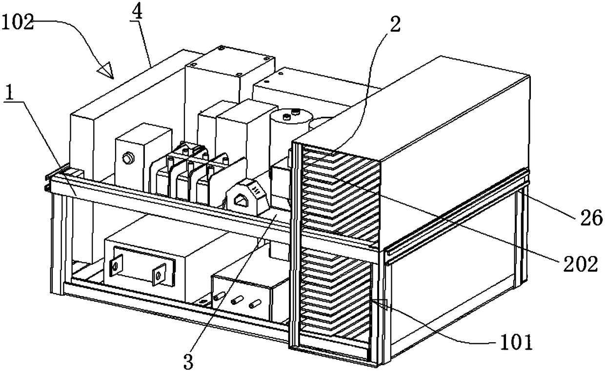
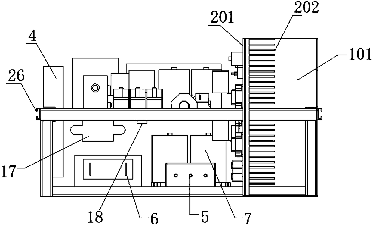
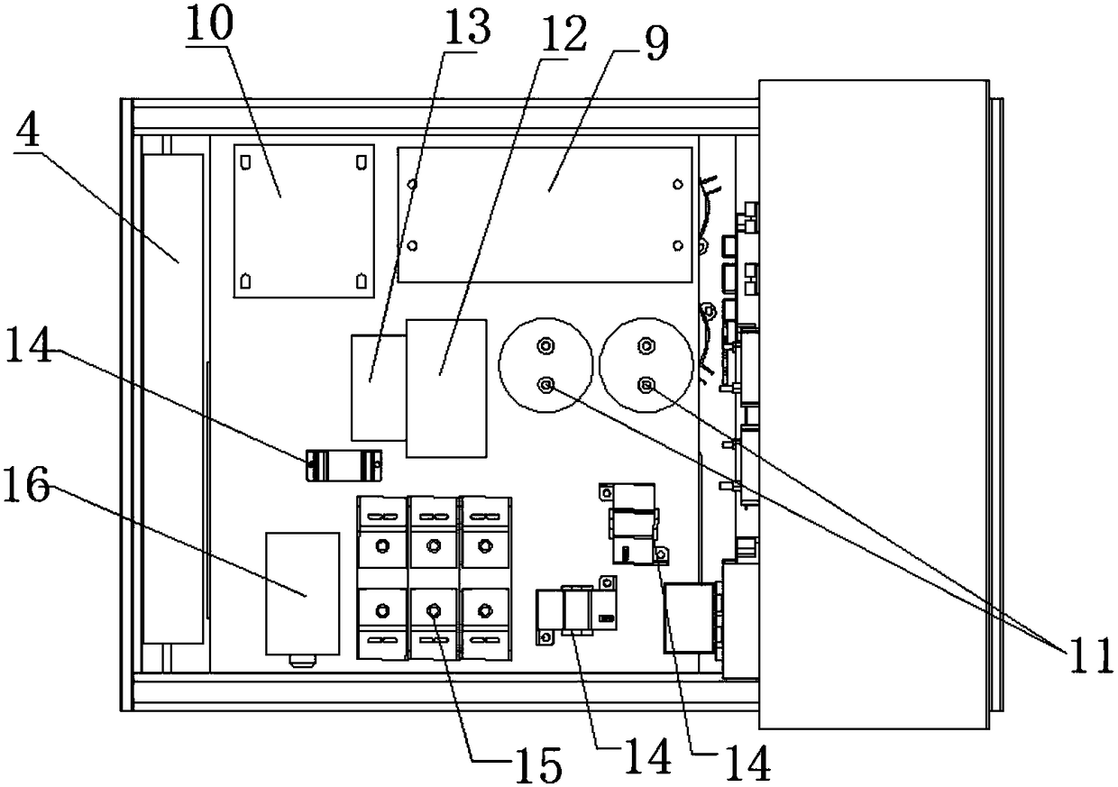
[0018] Such as figure 1 , figure 2 , image 3 , Figure 4 with Figure 5 As shown, an open charger includes a mounting frame 1 and a radiator 2, and the radiator divides the mounting frame into two parts, a cooling air duct 101 and a device mounting area 102, and the radiator is mainly composed of a mounting surface 201 and a plurality of cooling fins 202 extending from the mounting surface, the mounting surface faces the device mounting area, the cooling fins extend into the cooling air duct, and the cooling air duct consists of several housings Surrounded by the installation surface of the radiator, and communicated from one side of the radiator to the other side; among the several devices that make up the charging circuit of the charger, the componen...


PUM


Abstract

The invention discloses an open charging machine. A shell with high IP protection level requirements is omitted, and the charging machine can be directly installed in a train traction converter. By designing a heat dissipation air passage on one side of a radiator, a cold zone in the traction converter can be used for cooling fins of the radiator, and the heat dissipation efficiency is improved. By designing upper and lower mounting plates on the other side of the radiator, components, which need heat dissipation, among multiple components constituting a charging circuit of the charging machine are mounted on a mounting surface of the radiator, and main control boards are mounted on the sides, in the reverse direction of the radiator, of the mounting plates, so that the space is fully utilized to mount components constituting the charging circuit of the charging machine, and convenient wiring is achieved. The open charging machine has a very compact structure, the space occupied by thecharging machine is optimized to the greatest extent, the size and weight of the charging machine are greatly reduced, and the requirements for weight reduction of a train are met.

Description

technical field [0001] The invention relates to a charger for trains, in particular to an open charger with small volume and low weight. Background technique [0002] The charger is used in all high-speed rail, bullet trains, vehicles and related facilities powered by batteries, and is an important power supply equipment. Chargers usually include charging circuits such as input circuits, full-bridge inverter circuits, output circuits, and control circuits, involving rectifier bridge modules, input contactors, filters, current limiting resistors, discharge resistors, supporting capacitors, IGBT modules, and IGBT absorbers. Capacitors, voltage and current transformers, driver boards, main control boards, terminal blocks, high-frequency transformers, output filter inductors, filter capacitors, EMI filters and other devices, because some devices cannot be placed in a humid environment, usually need to use The shell forms a closed cavity to meet the needs of high protection leve...

Claims


Application Information

Patent Timeline
IPC IPC(8): H02J7/00H05K7/20
CPCH02J7/0042H05K7/20863
Inventor 洪振海杨磊张陈张松范跃坤潘贻丰
Owner 苏州市万松电气有限公司
Why Eureka
Try Eureka