Residual film recycling device and residual film recycler

A technology of residual film recovery and mulch film, which is applied in the field of residual film recovery device and residual film recovery machine, can solve the problems of low recovery rate of residual film, residual film floating away, falling on other parts of the equipment, etc.

Pending Publication Date: 2018-07-31
新疆郅拓农机科技有限公司
View PDF0 Cites 3 Cited by
  • Summary
  • Abstract
  • Description
  • Claims
  • Application Information

AI Technical Summary

Problems solved by technology

However, the used plastic film needs to be removed from the soil, and the plastic film remaining in the soil will gradually decompose, and the decomposed harmful components will be stored in the soil, which will have a negative impact on subsequent planting
[0003] In the prior art, the equipment for removing plastic film in the soil is mainly the spring-tooth type residual film recycling machine, but the spring teeth of the spring-tooth type residual film recovery machine are elastic, so that the spring teeth can easily make the residual film Floating, sometimes falling on other parts of the equipment, time-consuming and laborious to clean up, sometimes falling back into the soil, making the recovery rate of residual film low, still requiring a lot of manual labor
The finger-type residual film recovery machine uses the rake machine to lift the film, and integrates the residual film, weeds, and vines on the surface of the land into strips. Although the recovery rate of the residual film is high, it cannot directly collect the plastic film. inefficiency

Method used


Image

  • Residual film recycling device and residual film recycler
  • Residual film recycling device and residual film recycler

Examples


Embodiment Construction

[0021] In order to further explain the technical means and effects of the present invention to achieve the intended purpose of the invention, the specific implementation, structure, characteristics and effects of the residual film recovery device proposed according to the present invention will be described below in conjunction with the accompanying drawings and preferred embodiments. Details are as follows.

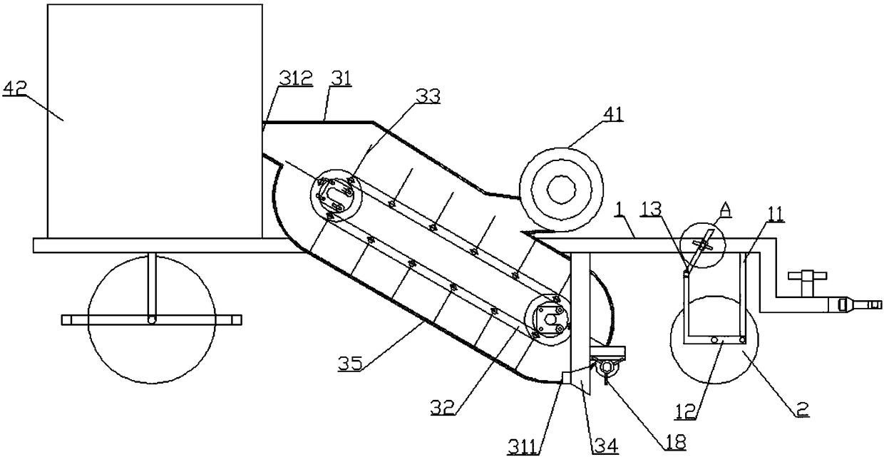
[0022] Such as figure 1 Shown, a kind of residual film recycling device comprises:

[0023] Frame 1, above-mentioned frame 1 is provided with ground wheel 2, is used for supporting and walking;

[0024] The film picking part, including the cover body 31 and the conveyor belt, is fixedly connected to the above-mentioned frame 1; the above-mentioned conveyor belt is arranged in the above-mentioned cover body 31; the above-mentioned cover body 31 has an inlet 311 and an outlet 312, and the above-mentioned inlet 311 is provided with a film lifting shovel 34 , the above-men...


PUM


Abstract

The invention provides a residual film recycling device. According to the main technical scheme, ground wheels are arranged on a frame and are used for supporting and walking; a film lifting part comprises a cover body and a conveying belt; the conveying belt is arranged in the cover body; the cover body is provided with an inlet and an outlet, the inlet is provided with a film lifting shovel, andthe film lifting shovel is used for lifting mulching film in soil or the surface of the soil into the cover body; the conveying belt is provided with multiple thorns, and the thorns are used for lifting the mulching film in the cover body; a baseboard of the cover body is provided with multiple holes and is used for shaking the soil off; a collecting part comprises a blower and a collecting box;an opposite first end and second end are arranged at the bottom of the collecting box, and the first end is hinged to a frame; the outlet is movably connected to the collecting box; the blower is arranged on the cover body, and the air outlet direction of the blower faces the conveying belt, so that the film on the conveying belt is separated from the thorns, flies out of an outlet and enters thecollecting box; one end of a lifting oil cylinder is fixedly connected to the second end, and the other end of the lifting oil cylinder is fixedly connected to the frame; when the lifting oil cylinderlifts, the collecting box rotates around the first end, and the mulching film in the collecting box is removed.

Description

technical field [0001] The invention relates to the field of residual film recovery, in particular to a residual film recovery device and a residual film recovery machine. Background technique [0002] Mulch film is a very commonly used thing in agricultural planting. It looks like a thin layer, but it has a considerable effect. Mulching film can not only improve ground temperature, water retention, soil conservation, fertilizer conservation and improve fertilizer efficiency, but also has many functions such as weed control, pest control, drought and waterlogging resistance, salt suppression and seedling protection, improvement of light and heat conditions near the ground, and sanitation and cleaning of products. . For those seedlings just unearthed, it has the functions of mulching roots and promoting growth. For my country's three northern regions, low temperature, little rain, drought and poor ridges, short frost-free period and other factors that limit agricultural dev...

Claims


Application Information

Patent Timeline
IPC IPC(8): A01B43/00
CPCA01B43/00
Inventor 耿锋利
Owner 新疆郅拓农机科技有限公司
Why Eureka
Try Eureka