
Group welding method of auxiliary steel box beam group welding device

A technology of steel box girder and auxiliary group, which is applied in the direction of auxiliary devices, auxiliary welding equipment, welding/cutting auxiliary equipment, etc., can solve problems such as damage to both side wall panels, and achieve reduced workload, convenient operation, and strong applicability Effect

Active Publication Date: 2018-07-31
WUHAN HAIWANG MECHANICAL & ELECTRICAL ENGTECH
View PDF8 Cites 5 Cited by
  • Summary
  • Abstract
  • Description
  • Claims
  • Application Information

AI Technical Summary

Problems solved by technology

[0004] In view of the defects existing in the prior art, the object of the present invention is to provide a welding method for an auxiliary welding device for steel box girders, which can assist in the welding of steel box girders of various specifications and sizes, and clamp and fix large areas. The method replaces the point-fixed position-limiting method in the traditional method, and solves the problem of fixing damage to the side walls

Method used


Image

  • Group welding method of auxiliary steel box beam group welding device
  • Group welding method of auxiliary steel box beam group welding device
  • Group welding method of auxiliary steel box beam group welding device

Examples


Embodiment Construction

[0034] Embodiments of the present invention will be described in further detail below in conjunction with the accompanying drawings.

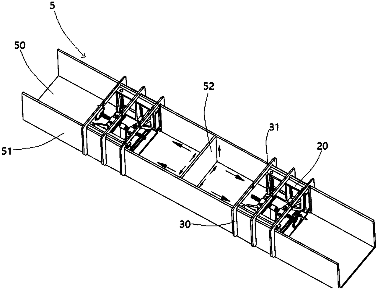
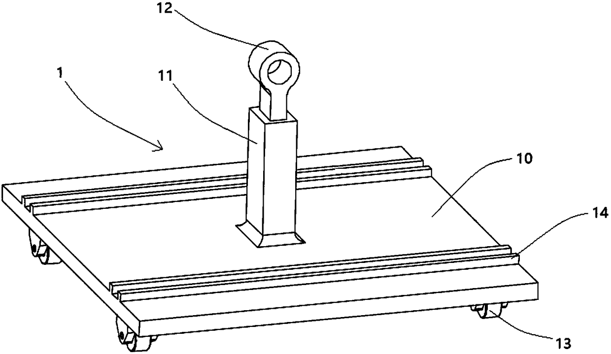
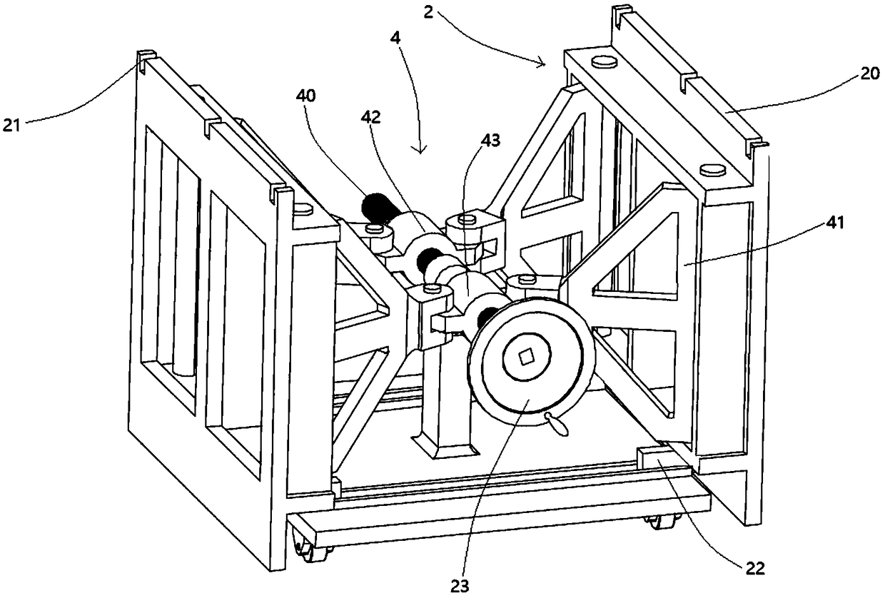
[0035] see Figure 1-Figure 4 As shown, the embodiment of the present invention provides a welding assembly method of an auxiliary assembly welding device of a steel box girder. The auxiliary assembly welding device is mainly used for assisting the assembly welding of the steel box girder 5 . The main body of the steel box girder 5 is generally rectangular, and mainly includes a bottom plate 50 at the bottom, wall plates 51 on both sides of the bottom plate 50, a partition plate 52 between the two side wall plates 51, and a panel section at the top. The plates 51 are parallel to each other and perpendicular to the bottom plate 50. The steel box girder auxiliary welding device is mainly used for clamping and fixing the side wall plates 51, so that they are welded and fixed when they are kept perpendicular to the bottom plate 50, and the wall pla...


PUM


Abstract

The invention discloses a group welding method of an auxiliary steel box beam group welding device and provides an auxiliary steel box beam group welding device. The auxiliary group welding device comprises a machine frame, a compressing assembly, at least one limiting clamp and a driving mechanism, wherein the compressing assembly comprises two compressing disks which are arranged at intervals; the limiting clamp comprises two limiting plates, and the two limiting plates are respectively arranged on the two sides of the compressing assembly; the driving mechanism is used for driving the compressing disks to move in the direction close to or far from the limiting clamp. Two auxiliary group welding devices are arranged at intervals in the length direction of a steel box beam bottom plate, and steel box beam wall plates on the two sides of the steel box beam bottom plate are respectively arranged between the compressing disks and the limiting plates; by adjusting the distance between thetwo limiting plates, the limiting plates can abut against the steel box beam wall plates; the driving mechanism is used for driving the compressing disks, so that the compressing disks and the limiting plates can clamp the steel box beam wall plates, and the steel box beam wall plates can be welded to the steel box beam bottom plate. The auxiliary steel box beam group welding device disclosed bythe invention can help group welding of varieties of steel box beams of different specifications and dimensions and solves the problem of fixing damage caused by a point fixing and limiting mode to the wall plates on the two sides.

Description

technical field [0001] The invention relates to the field of steel box girder manufacturing, in particular to a welding method for an auxiliary welding assembly device of a steel box girder. Background technique [0002] Rectangular steel box girder is one of the commonly used structures in steel structure engineering. It is generally welded by the bottom plate, panel segments, side wall plates and middle partitions. Compared with cast-in-place concrete beams, it has lighter weight and is The advantages of less environmental factors and higher strength are now being used more and more in large structures such as large bridges, municipal venues, skyscrapers, and wind tunnels. With the upgrading of product technology, the products of rectangular steel box girder structure are gradually developing towards large-scale and refined. The overall deformation control of rectangular steel box girder after welding is becoming more and more strict. , What kind of process to achieve hig...

Claims


Application Information

Patent Timeline
Patent Type & Authority Applications(China)
IPC IPC(8): B23K37/04
CPCB23K37/0435
Inventor 杨国强
Owner WUHAN HAIWANG MECHANICAL & ELECTRICAL ENGTECH
Learn More