Bolt hole machining device for die machining

A technology for machining and processing devices, applied in the field of bolt hole processing devices for mold machining, can solve the problems of excessively fast feed of drill bits and broken ends of drill bits, and achieve the effects of reducing the risk of fracture, improving efficiency and novel structure

Inactive Publication Date: 2018-07-31
单义丹
View PDF7 Cites 26 Cited by
  • Summary
  • Abstract
  • Description
  • Claims
  • Application Information

AI Technical Summary

Problems solved by technology

[0003] In the mold processing process, it is often necessary to process the bolt holes of the mold. In the bolt hole processing process of the existing mold, different clamping tasks need to be exchanged for molds of different specifications during processing, and the existing devices are not used during processing. It is often the case that the drill bit is fed too fast and the drill bit breaks

Method used


Image

  • Bolt hole machining device for die machining
  • Bolt hole machining device for die machining
  • Bolt hole machining device for die machining

Examples


Embodiment Construction

[0018] The technical solution of this patent will be further described in detail below in conjunction with specific embodiments.

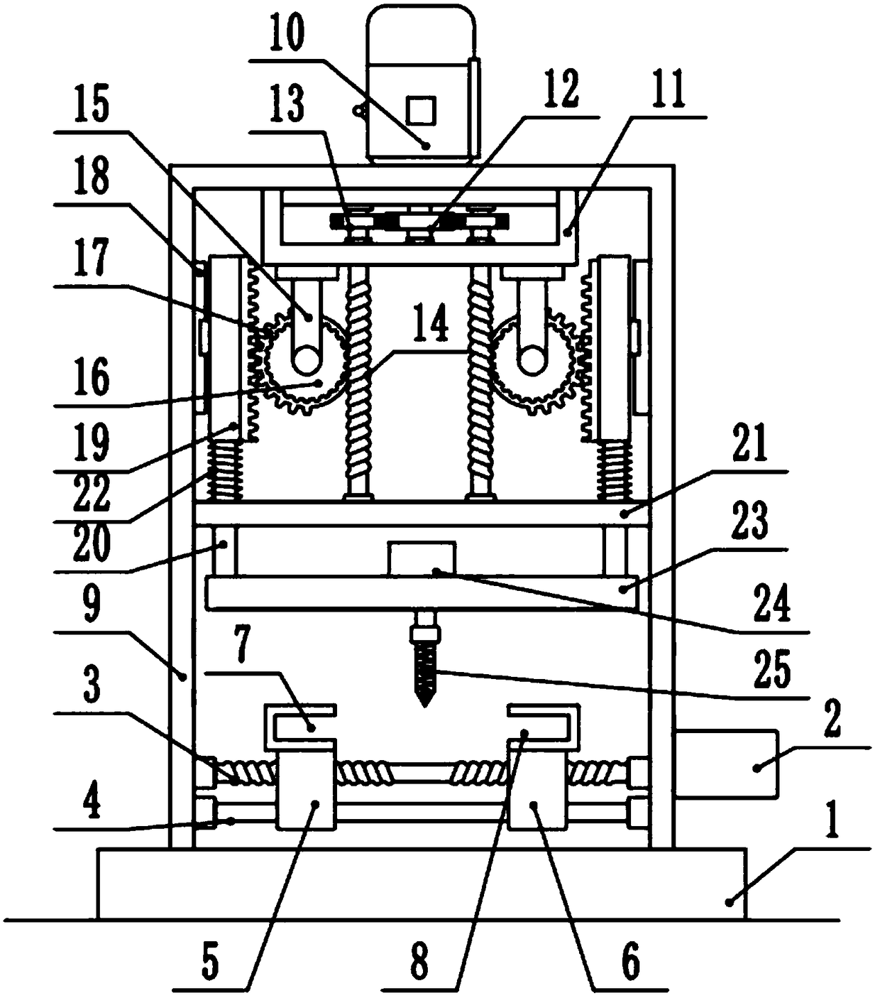
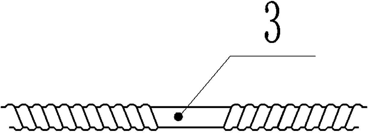
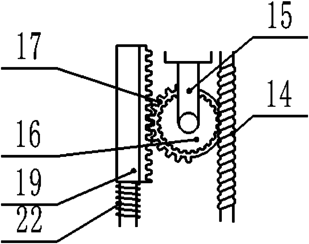
[0019] see Figure 1-3 , a bolt hole processing device for mold machining, comprising a base 1, a clamping motor 2, a left jaw 7, a right jaw 8, a main drive motor 10, a lifting frame 23 and a drilling motor 24, the platform 3 The upper surface is provided with a main bracket 9, and the main bracket 9 and the platform 3 are fixedly connected by screws. The right side of the main bracket 9 is fixed with a clamping motor 2, and the clamping motor has 2 servo motors, and the output shaft of the clamping motor 2 Horizontally to the left and penetrate the inside of the main bracket 9, the left end of the output shaft of the clamping motor 2 is fixedly installed with a ball screw 3 through a coupling, and the other end of the ball screw 3 is installed on the main bracket 9 through a bearing rotation. Both the left and right parts of the rod 3 are tapped...


PUM


Abstract

The invention discloses a bolt hole machining device for die machining. The bolt hole machining device comprises a clamping motor, a left clamping jaw, a right clamping jaw, a main driving motor, a lifting frame and a drilling motor, wherein a main support is arranged on the upper surface of a platform, the clamping motor is fixedly installed on the right side of the main support, the left end ofthe output shaft of the clamping motor is fixedly provided with a ball screw through a coupler, a left sliding block and a right sliding block are installed on the left portion and the right portion of a ball screw in a threaded mode, and the left clamping jaw and the right clamping jaw are fixedly arranged on the upper side of the left sliding block and the upper side of the right sliding block through screws respectively. The right sliding block is novel in structure, the distance between the left sliding block and the right sliding block is adjusted, the clamping work of molds with different specifications can be met, the universality of the device is greatly improved, and the mold does not need to be replaced during machining; and through the cooperation of a half gear and a sliding rack, a drill bit can move up and down continuously, and compared with a one-time drilling mode, the drill bit can be effectively protected in a continuous pressurization and continuous drilling mode, and the fracture risk of the drill bit is reduced.

Description

technical field [0001] The invention relates to the field of motors, in particular to a bolt hole processing device for mold machining. Background technique [0002] Mold, various molds and tools used in industrial production for injection molding, blow molding, extrusion, die-casting or forging forming, smelting, stamping and other methods to obtain the required products. In short, a mold is a tool used to make shaped objects. This tool is composed of various parts, and different molds are composed of different parts. It mainly realizes the processing of the shape of the article through the change of the physical state of the formed material. Under the action of external force, the blank becomes a tool with a specific shape and size. Widely used in blanking, die forging, cold heading, extrusion, powder metallurgy parts pressing, pressure casting, and compression molding or injection molding of engineering plastics, rubber, ceramics and other products. The mold has a spec...

Claims


Application Information

Patent Timeline
Patent Type & Authority Applications(China)
IPC IPC(8): B23Q3/06B23Q5/28B23Q5/48B23B47/20
CPCB23Q3/062B23Q5/28B23Q5/48
Inventor 单义丹
Owner 单义丹
Why Eureka
Try Eureka