Runner blade convoluting mechanism

A runner blade and blade technology, which is applied in the field of runner blade gyratory mechanism, can solve the problem of high leakage value between the blade and the inner wall of the stator, and achieve the effects of improving service life, improving energy efficiency and stabilizing movement structure.

Inactive Publication Date: 2018-07-31
周觉明
View PDF0 Cites 4 Cited by
  • Summary
  • Abstract
  • Description
  • Claims
  • Application Information

AI Technical Summary

Problems solved by technology

[0002] At present, the sliding vane rotary motion mechanism used in volumetric fluid machinery has the advantages of small size, light weight and high volumetric efficiency, and is widely used in fluid machinery such as fans, pumps, compressors, hydraulic and pneumatic motors; the slide of the sliding vane rotary motion mechanism There is high-speed contact friction between the blade and the stator, and the leakage value between the blade and the inner wall of the stator is relatively high, resulting in greater wear and energy loss

Method used


Image

  • Runner blade convoluting mechanism
  • Runner blade convoluting mechanism
  • Runner blade convoluting mechanism

Examples


no. 1 example

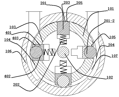
[0039] Such as figure 1 As shown, a runner 103 is installed on the drive shaft 102 of the rotor 101, four sliding blade grooves 105 are axially opened on the column 104 of the runner 103, and the runner 103 bearing support is eccentrically mounted on the cylinder 107 of the stator 106. in. The blade 201 is installed in the sliding blade groove 105 of the runner 103. The blade 201 is under the action of the centrifugal force of the rotation of the runner 103 or the elastic force of the spring 202 installed in the sliding blade groove 105. 203 is in line contact with the inner circular arc wall 204 of the cylinder 107. The rotor 101 rotates, and the outer arc surface 203 at the top of the blade 201 moves and circulates in contact with the inner arc wall surface 204 of the cylinder 107, and an arc surface 205 is formed on the outer arc surface 203 of the blade 201. The contact area of ​​the arc surface 205 is The size is proportional to the arc diameter of the outer arc surface 2...


PUM


Abstract

The invention provides a runner blade convoluting mechanism. Blades are installed in sliding vane grooves of a turning wheel. Under the action of rotational centrifugal force of the turning wheel or elastic force of springs installed in the sliding vane grooves, the outer arc surfaces of the top ends of the blades are in line contact with the inner arc wall surface of a cylinder body. The structures of the blades are rolling blades or sliding blades, the rolling blades are in a cylindrical shape, and the rolling blades roll in the sliding vane grooves of the rotating wheel. The sliding bladesslide in the sliding vane grooves of the rotating wheel, and the outer arc surfaces and the lower arc surfaces of the sliding blades are of the same center of a circle. Through the technical improvement, a blade meshing control device changes the contact rotary motion between the blades and the cylinder body into the meshing rotary motion, and the rotational speed is not affected by the speed of acontact line. The performance of pumps, hydraulic power machines, pneumatic machines, compressors, expansion power machines and engines in the technical field of fluid machinery is improved.

Description

Technical field [0001] The invention is a runner blade turning mechanism suitable for a rotary positive displacement fluid machine, and relates to the technical fields of mechanical manufacturing such as fans, pumps, hydraulic motors, pneumatic motors, compressors, expansion power machines, and engines. Background technique [0002] The sliding vane rotating mechanism currently used in positive displacement fluid machinery has the advantages of small size, light weight and high volumetric efficiency. It is widely used in fluid machinery such as fans, pumps, compressors, hydraulic pneumatic motors, etc.; the sliding vane rotating mechanism There is high-speed contact friction between the blade and the stator, and the leakage value between the blade and the inner wall of the stator is relatively high, resulting in greater wear and energy loss. In order to solve the above shortcomings, there is an urgent need for a motion mechanism with rolling or meshing motion between the sliding ...

Claims


Application Information

Patent Timeline
Patent Type & Authority Applications(China)
IPC IPC(8): F01C1/344F01C1/356F03C2/30F04C2/344F04C2/356F04C18/344F04C18/356
CPCF01C1/3442F01C1/3564F03C2/304F04C2/3442F04C2/3564F04C18/3441F04C18/3564
Inventor 周觉明杨鼎
Owner 周觉明
Why Eureka
Try Eureka