Method and system for automatic bond arm alignment

A bonding and bonding head technology, which is applied in the direction of tin feeding devices, electrical components, circuits, etc., can solve problems such as time-consuming, mechanical adjustment or misreading of measured values, and achieve risk reduction, time reduction, and complete electrical connection Effect

Active Publication Date: 2018-07-31
ASM TECH SINGAPORE PTE LTD
View PDF7 Cites 2 Cited by
  • Summary
  • Abstract
  • Description
  • Claims
  • Application Information

AI Technical Summary

Problems solved by technology

[0005] A problem associated with existing adjustment methods is that the iterative process of mechanical and manual adjustment after inclination measurement is qualitative and time consuming
There is also a risk of human error, e.g. due to mechanical adjustments in the wrong direction or misinterpretation of measured values

Method used


Image

  • Method and system for automatic bond arm alignment
  • Method and system for automatic bond arm alignment
  • Method and system for automatic bond arm alignment

Examples


Embodiment Construction

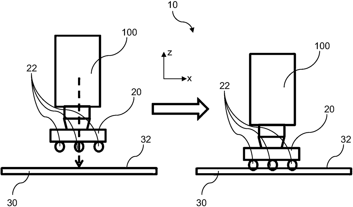
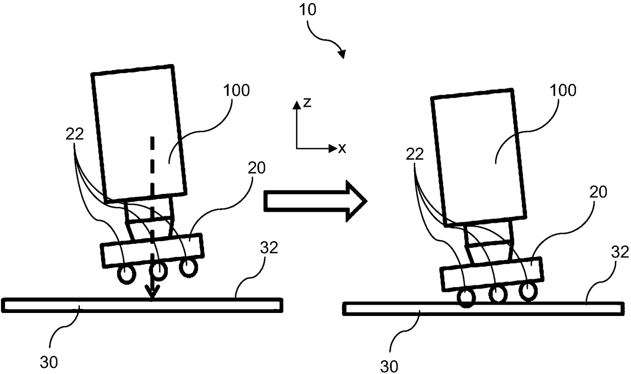
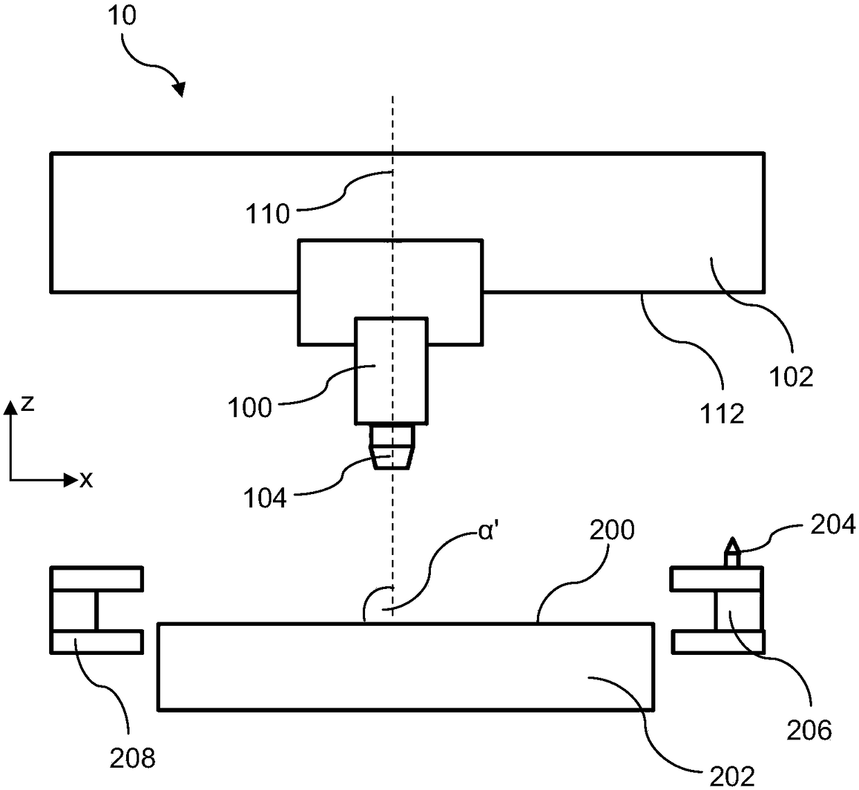
[0031] In the present invention, description of a given element, or consideration or use of a particular element number in a particular figure, or reference thereto in corresponding descriptive material may cover the same, Equivalent or similar elements or element numbers. The use of " / " in a figure or related text should be understood to mean "and / or" unless otherwise indicated. Recitations herein of specific values ​​or ranges of values ​​are understood to include or recitations of approximate values ​​or ranges of values. For brevity and clarity, the description of embodiments of the invention is directed to methods and systems for automatically aligning a bond arm relative to a bond support surface, with reference to the accompanying drawings. It should be understood that the drawings may not be drawn to scale and may not be relied upon to show or determine specific sizes and / or dimensions.

[0032] While various aspects of the invention will be described in conjunction ...


PUM


Abstract

A method, as well as a system implementing the method, for automatically aligning a bond arm with respect to a bonding support surface for supporting a substrate during a bonding process. The method comprises: rotating the bond arm for a first revolution around a longitudinal axis through a bond head moveably coupled to the bond arm, the first revolution including a plurality of predefined rotaryangular positions; pausing the rotation of the bond arm at each of the plurality of rotary angular positions; determining a tilt angle of the bond arm relative to the bonding support surface during each pause at the respective rotary angular position; and selecting the rotary angular position of the bond arm which has a tilt angle that satisfies a predefined specification such that the bond arm isaligned substantially perpendicular to the bonding support surface.

Description

technical field [0001] The present invention generally relates to methods and systems for automated alignment of bond arms. More specifically, the present disclosure describes embodiments of a method and system for implementing the method for automatically moving a bonding arm relative to a bonding support surface for supporting a substrate during a bonding process. ground alignment. Background technique [0002] Flip chip bonding is a process used to interconnect semiconductor devices, components or dies to circuit boards, wafers or substrates. The semiconductor device has solder bumps deposited on the die pads on the top surface of the semiconductor device. Then, the semiconductor device is flipped over by the flip arm or actuator so that the top surface is facing down and the chip pads are aligned with the pad surface of the substrate. The bond arms are moved to bond the semiconductor device to the substrate, and the solder reflows to complete the interconnection. [...

Claims


Application Information

Patent Timeline
Patent Type & Authority Applications(China)
IPC IPC(8): H01L21/68H01L21/60
CPCH01L21/68H01L24/80H01L2224/8015H01L2224/80121H01L24/81H01L2224/75753H01L2224/81121H01L2224/81191H01L24/75H01L2224/75823B23K2101/40H01L21/563H01L21/67092H01L21/67121H01L24/74B23K1/0016B23K3/0623H01L2224/75702H01L2224/759B23K3/00
Inventor 胡瑞璋唐良红丘允贤
Owner ASM TECH SINGAPORE PTE LTD
Why Eureka
Try Eureka