Supercharge Your Innovation With Domain-Expert AI Agents!

Differential amplifier

A technology of differential amplifiers and amplifying circuits, applied in the direction of differential amplifiers, amplifiers, DC-coupled DC amplifiers, etc., to achieve the effect of reducing voltage and avoiding deadlock state

Inactive Publication Date: 2018-07-31
SEMICON MFG INT (SHANGHAI) CORP +1
View PDF4 Cites 5 Cited by
  • Summary
  • Abstract
  • Description
  • Claims
  • Application Information

AI Technical Summary

Problems solved by technology

[0004] However, the above differential amplifier cannot completely avoid the deadlock condition

Method used


Image

  • Differential amplifier
  • Differential amplifier
  • Differential amplifier

Examples


Embodiment Construction

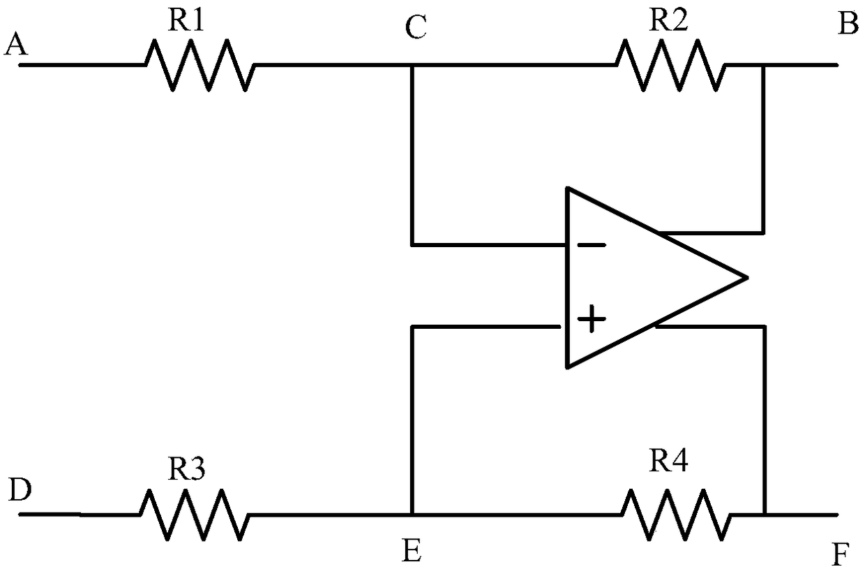
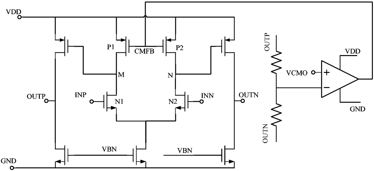
[0021] figure 1 shows a current circuit schematic diagram of a differential amplifier, figure 2 Yes figure 1 The specific circuit structure diagram of the differential amplifier in is a fully differential two-stage operational amplifier with NMOS transistors as input pairs. Among them: point B corresponds to the output terminal OUTP, point C corresponds to the input terminal INP of the positive phase signal to be compared, point E corresponds to the input terminal INN of the negative phase signal to be compared, point F corresponds to the output terminal OUTN, and the ports corresponding to points A and D are in figure 2 not shown in

[0022] If the common mode signal output by the differential amplifier is low, it can be assumed that the voltage of the output common mode signal is the reference wire voltage GND. Under the action of the common mode amplifier circuit (Common Mode amplifier), the common mode feedback signal (Common Mode Feedback Circuit, CMFB) will be pulle...


PUM


Abstract

A differential amplifier includes a common mode amplifying circuit and a differential mode amplifying circuit that are sequentially coupled, wherein the common mode amplifying circuit includes non-inverting and inverting input ends and an output end for outputting common mode feedback signals, the differential mode amplifying circuit includes a feedback signal input end, first and second input ends, first-stage and second-stage amplifying circuits, and first and second output ends, and the feedback signal input end is coupled to the output end of the common mode amplifying circuit; the first input end is coupled to the first-stage amplifying circuit, the second input end is coupled to the first-stage amplifying circuit, and the first input end and the second input end separately input signals to be compared with opposite phases; the first-stage amplifying circuit inputs the amplified signals to be compared to the second-stage amplifying circuit through the output end of the first-stageamplifying circuit; a bias current circuit is arranged between the output end of the first-stage amplifying circuit and a reference ground wire; and the second-stage amplifying circuit further amplifies the signals to be compared and outputs a common mode signal. By adopting the above scheme, the occurrence of a deadlock state of the differential amplifier can be avoided.

Description

technical field [0001] The invention relates to the technical field of electronic circuits, in particular to a differential amplifier. Background technique [0002] Differential Amplifier (Differential Amplifier) ​​is a direct-coupled amplifier with very small zero point drift. It is often used to amplify the difference between two input voltages, also known as differential amplifier. The differential amplifier is a basic unit of various integrated circuits, but the output / input voltage of the differential amplifier in normal operation may have a relatively large instantaneous jump due to the initial voltage of the input node being too high when the circuit is powered on, or physical interference. Changes and other reasons cause the differential amplifier circuit to appear in a deadlock state, which in turn leads to the failure of the differential amplifier function. [0003] In order to avoid the deadlock state of the differential amplifier, currently, a reset circuit is p...

Claims


Application Information

Patent Timeline
Patent Type & Authority Applications(China)
IPC IPC(8): H03F3/45H03F1/34
CPCH03F1/342H03F3/45197
Inventor 刘飞唐华荀本鹏杨海峰徐丽
Owner SEMICON MFG INT (SHANGHAI) CORP
Features
  • R&D
  • Intellectual Property
  • Life Sciences
  • Materials
  • Tech Scout
  • Unparalleled Data Quality
  • Higher Quality Content
  • 60% Fewer Hallucinations
Learn More