A kind of imaging system and method
An imaging system and image technology, applied in the field of computational vision, can solve the problems of increasing equipment cost, inconvenient system deployment and movement, increasing system weight and volume, etc., to achieve the effect of rapid acquisition
- Summary
- Abstract
- Description
- Claims
- Application Information
AI Technical Summary
Problems solved by technology
Method used
Image
Examples
Embodiment 1
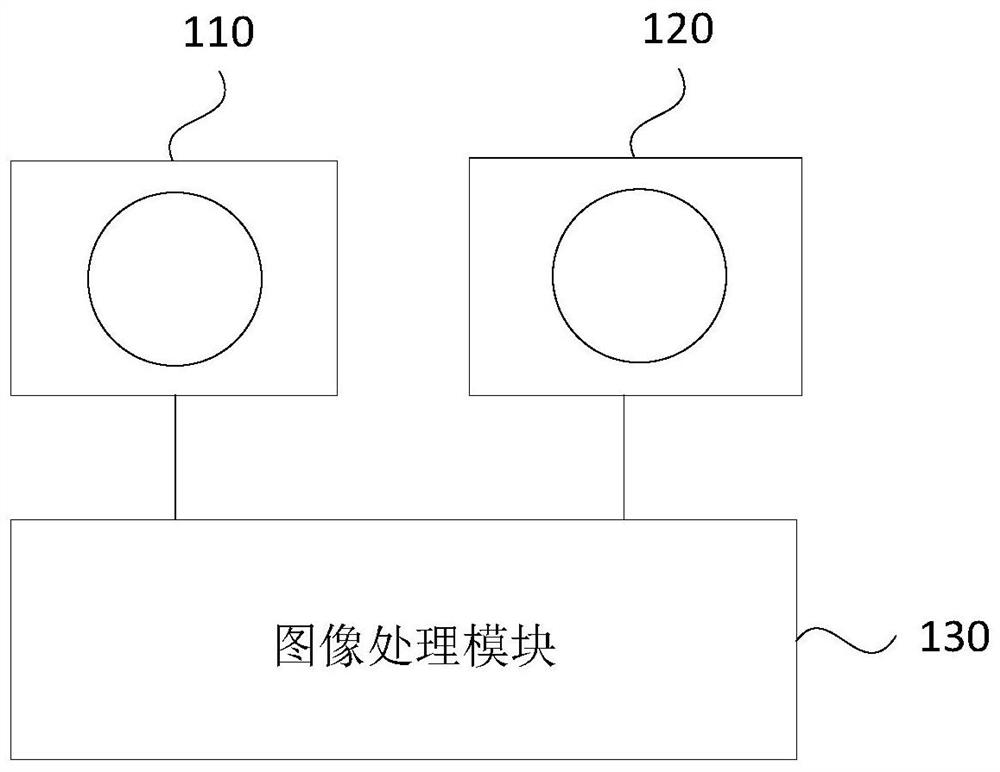
[0023] figure 1 A schematic structural diagram of an imaging system provided in Embodiment 1 of the present invention, such as figure 1 As shown, the imaging system includes: a first scale camera 110 , a second scale camera 120 and an image processing module 130 .
[0024] Wherein, the first-scale camera 110 is a large-scale wide-field-of-view low-resolution camera, and the second-scale camera 120 is a small-scale narrow-field-of-view high-resolution camera. In this embodiment, once the shooting position of the first-scale camera 110 is determined, it is fixed, and it is used for real-time acquisition of the first-scale image with the first resolution; the shooting position of the second-scale camera 120 is determined according to the desired The actual scene changes in real time, and is used to acquire a second-scale image with a second resolution corresponding to the target area in the current first-scale image. It should be noted here that the installation of the first-sc...
Embodiment 2
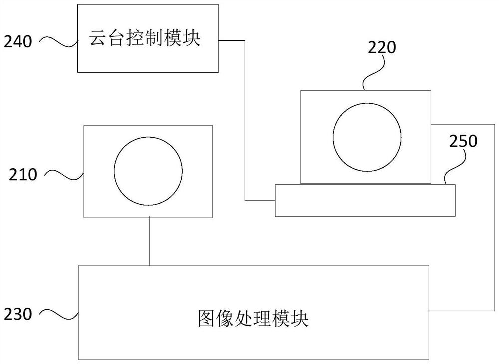
[0036] figure 2 It is a schematic structural diagram of an imaging system provided by Embodiment 2 of the present invention. This embodiment further optimizes the imaging system on the basis of the foregoing embodiments. like figure 2 As shown, the system specifically includes: a first-scale camera 210 , a second-scale camera 220 , an image processing module 230 , a pan-tilt control module 240 and a pan-tilt 250 .
[0037]Among them, the first scale camera 210 is used to acquire the first scale image with the first resolution in real time; the second scale camera 220 is used to acquire the image with the second resolution corresponding to the target area in the current first scale image. The second scale image; the image processing module 230 is used to obtain a third scale image with a third resolution by using the current first scale image and the second scale image based on the first preset algorithm; the PTZ control module 240 uses To calculate the moving azimuth and m...
Embodiment 3
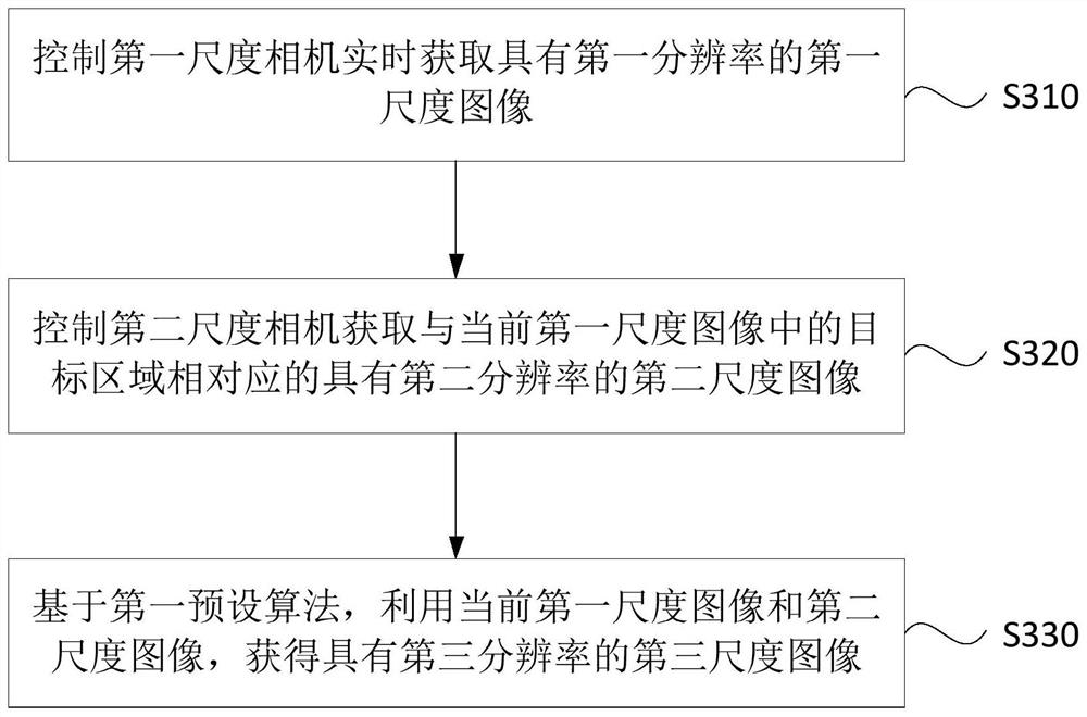
[0055] image 3 It is a flow chart of an imaging method provided by Embodiment 3 of the present invention. This method is applicable to the situation where images or videos with high resolution and large field of view need to be obtained, and this method can be executed by an imaging system. like image 3 As shown, the method specifically includes:
[0056] S310. Control the first-scale camera to acquire a first-scale image with a first resolution in real time.
[0057] Wherein, the scale is equivalent to the field of view range of the camera. If the camera is a camera with a wide field of view, the scale of the camera is a large scale, and if the camera is a camera with a narrow field of view, the scale of the camera is a small scale.
[0058] In this embodiment, the first-scale camera is a large-scale wide-field-of-view low-resolution camera, which is used to acquire a first-scale image with a first resolution in real time, wherein the first-scale image with the first reso...
PUM
 Abstract
Description
Claims
Application Information
 - R&D
- Intellectual Property
- Life Sciences
- Materials
- Tech Scout
- Unparalleled Data Quality
- Higher Quality Content
- 60% Fewer Hallucinations
Browse by: Latest US Patents, China's latest patents, Technical Efficacy Thesaurus, Application Domain, Technology Topic, Popular Technical Reports.
© 2025 PatSnap. All rights reserved.Legal|Privacy policy|Modern Slavery Act Transparency Statement|Sitemap|About US| Contact US: help@patsnap.com


