
Magnetic fluid seal

A magnetic fluid and seal technology, applied in the direction of engine seals, bearing components, engine components, etc., can solve the problems of shortening the life of the sealing film, poor sealing performance of the sealing film, and different temperature environments.

Inactive Publication Date: 2018-07-31
EAGLEBURGMANN JAPAN
View PDF6 Cites 10 Cited by
  • Summary
  • Abstract
  • Description
  • Claims
  • Application Information

AI Technical Summary

Problems solved by technology

[0012] However, if a cooling flow path is provided in the axial center of the magnetic pole members arranged side by side in the axial direction as described in Patent Document 1, the magnetic pole on the inner side of the axial machine arranged between the high-temperature gas and the cooling flow path will The temperature environment of the component will be different from the temperature environment of the magnetic pole component on the axial atmospheric side arranged between the cooling flow path and the atmosphere
Therefore, when the flow rate of the coolant flowing in the cooling flow path is set to suit the temperature of one magnetic pole member on the high-temperature gas side, the temperature of the sealing film of the magnetic pole member on the atmospheric side becomes too low, and the high-temperature gas is cooled. , by-products are generated around the sealing film, and the by-products will enter the sealing film, which may lead to poor sealing performance of the sealing film
In addition, when the temperature is set in accordance with the magnetic pole member on the other atmospheric side, the temperature of the sealing film of the magnetic pole member on the high-temperature gas side becomes too high, and the base liquid of the magnetic fluid that exists to form the sealing film evaporates to cause the sealing film Possibility of poor sealing
In addition, the life of the sealing film may be shortened due to such deterioration of sealing performance.
In addition, the magnetic fluid seal using the radiator plate described in Patent Document 2 also has the same problem

Method used


Image

  • Magnetic fluid seal
  • Magnetic fluid seal
  • Magnetic fluid seal

Examples


Embodiment 1

[0037] First, the structure of the magnetic fluid seal of Example 1 will be described.

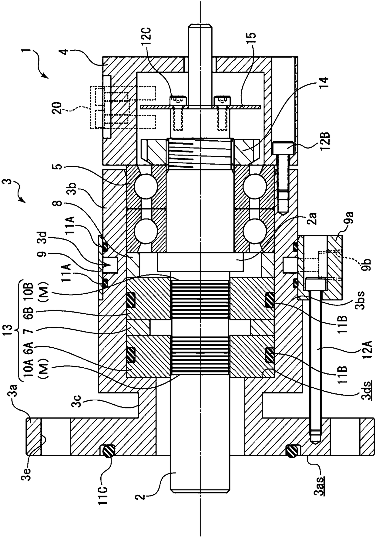
[0038] Such as figure 1 As shown, the magnetic fluid seal 1 of the present invention has a seal portion 13, and the seal portion 13 is composed of the following members as a member for performing a main function, that is, magnetic pole members 6A, 6B, which are mounted on a fluid machine The rotating shaft 2; the magnetic force generating part 7, which is arranged between the magnetic pole member 6A and the magnetic pole member 6B, can form a magnetic pole on the magnetic pole member 6A, 6B; and the magnetic fluid 10A, 10B, which can be formed along the magnetic pole member. The magnetic circuit between 6A, 6B and the rotary shaft 2 forms a sealing film M, M. In this way, the sealing film M formed along the rotating shaft 2 is used to form a connection between the rotating shaft 2 of the magnetic fluid seal 1 and the outer cylinder member 3 mounted on the casing (not shown) of the fluid ...

Embodiment 2

[0062] Next, the structure of the magnetic fluid seal of Example 2 will be described. In addition, the description of the same structure as that of the first embodiment is omitted.

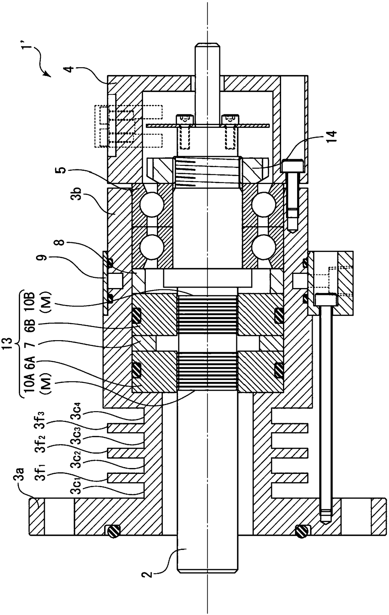
[0063] Such as figure 2 As shown, in the magnetic fluid seal 1' of Example 2, a small-diameter portion 3c is provided as a so-called heat sink between the flange portion 3a and the outer cylinder portion 3b. 1 、3c 2 、3c 3 、3c 4 and a circular flat plate 3f extending in the outer diameter direction between these small diameter portions 1 、3f 2 、3f 3 . By providing a plurality of small-diameter parts 3c like this 1 、3c 2 、3c 3 、3c 4 and multiple circular plates 3f 1 、3f 2 、3f 3 That is, the heat dissipation fins can increase the surface area between the flange portion 3a and the outer cylinder portion 3b, thereby achieving a more remarkable heat dissipation effect. That is, the small diameter portion 3c 1 、3c 2 、3c 3 、3c 4 Functioning as the heat insulating member of the present ...

Embodiment 3

[0065] Next, the structure of the magnetic fluid seal of Example 3 will be described. In addition, the description of the same structure as that of the first embodiment is omitted.

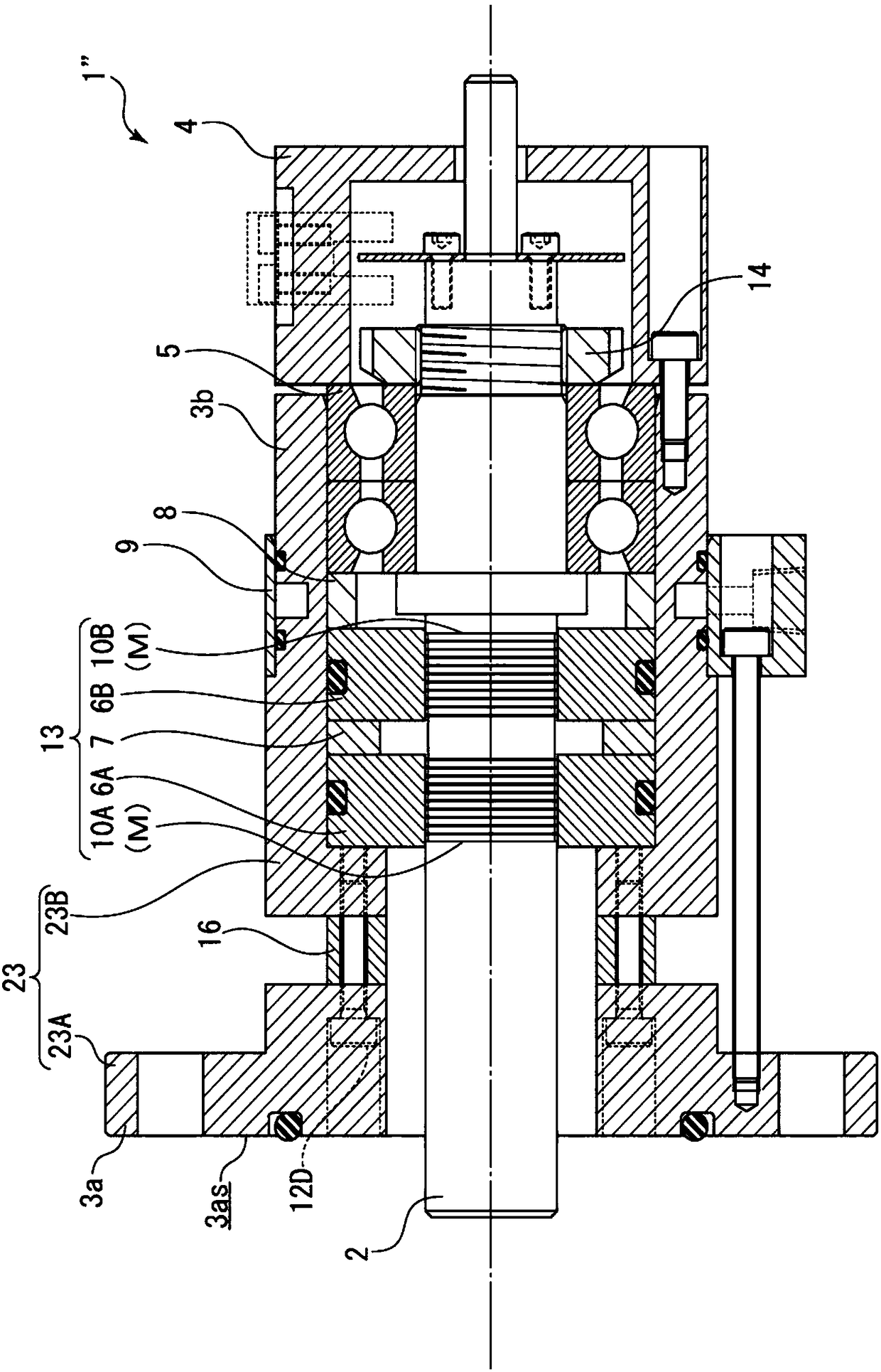
[0066] Such as image 3 As shown, the outer cylinder member 23 of the magnetic fluid seal 1" of Embodiment 3 is composed of independent members such as a flange member 23A and an outer cylinder member 23B that are independent of each other. The flange member 23A and the outer cylinder member 23B are formed in diameter The small-diameter member 16 whose upward diameter is smaller than that of the outer cylinder member 23B is interposed between the flange member 23A and the outer cylinder member 23B, and is fixed together by the hexagon bolt 12D inserted from the mounting surface 3as of the flange member 23A.

[0067]Here, the small-diameter member 16 is an annular member whose diameter in the radial direction is smaller than that of the outer cylinder member 23B, and its material may be a resin mo...


PUM


Abstract

Provided is a magnetic fluid seal in which a seal film formed in the axial direction serves as a structure that makes it possible to easily set a temperature environment, and in which said seal film has a long service life. The magnetic fluid seal (1) comprises: an outer cylinder member (3) in which a rotating shaft (2) extending from a housing for a fluid machine is accommodated, said outer cylinder member (3) comprising an attachment section (3a) for attachment to the housing; magnetic pole members (6A, 6B) that are arranged around the rotating shaft (2) accommodated in the outer cylinder member (3) and that form a magnetic circuit; and a seal film (M) that is magnetically connected on the magnet circuit, that is arranged between the magnetic pole members (6A, 6B) and the rotating shaft(2), that comprises magnetic fluids (10A, 10B), and that is formed in the axial direction. The outer cylinder member (3) comprises a heat blocking means (3c) for blocking heat transmitted in the axialdirection thereof and a cooling means (3d) for cooling the outer cylinder member (3). The attachment section (3a), the heat blocking means (3c), the seal film (M), and the cooling means (3d) are arranged in this order in the outer cylinder member (3) in the axial direction thereof.

Description

technical field [0001] The present invention relates to a magnetic fluid seal for use, for example, in high temperature environments. Background technique [0002] Conventionally, a magnetic fluid seal is known as a long-life and clean high-performance seal. This magnetic fluid seal is widely used in the manufacturing process of semiconductors and liquid crystals that require maintenance-saving and clean environments, and various coating and etching processes for them. [0003] The magnetic fluid seal seals the gap between the casing of the fluid machine and the rotary shaft with a sealing film formed of magnetic fluid formed between the magnetic pole member held fixed to the casing of the fluid machine and the rotary shaft. on the inside of the outer cylinder member. [0004] Although a sealing film is formed on these magnetic fluid seals, when the fluid sealed in the fluid machine is, for example, a high-temperature gas, heat is transferred from the high-temperature gas ...

Claims


Application Information

Patent Timeline
Patent Type & Authority Applications(China)
IPC IPC(8): F16J15/43F16C19/54F16C33/78F16C35/12F16C37/00F16C19/16
CPCF16C19/08F16C33/746F16C33/765F16C35/12F16C37/005F16C37/007F16C2300/62F16J15/43F16C33/78F16J15/162
Inventor 佐藤和彦
Owner EAGLEBURGMANN JAPAN
Learn More