
Coil former for an electrical coil assembly and method for producing an electrical coil assembly

A coil support and electric coil technology, which is applied in coil manufacturing, electromechanical devices, and motor generator manufacturing, can solve the problem of heat dissipation in areas where no castings are placed, and achieve improved heat dissipation

Active Publication Date: 2018-07-31
EGSTON SYST ELECTRONICS EGGENBURG
View PDF8 Cites 1 Cited by
  • Summary
  • Abstract
  • Description
  • Claims
  • Application Information

AI Technical Summary

Problems solved by technology

Such potting, however, does not penetrate the entire cavity, which leads to regions of the coil where no potting is arranged and corresponding disadvantages with regard to heat dissipation.

Method used


Image

  • Coil former for an electrical coil assembly and method for producing an electrical coil assembly
  • Coil former for an electrical coil assembly and method for producing an electrical coil assembly
  • Coil former for an electrical coil assembly and method for producing an electrical coil assembly

Examples


Embodiment Construction

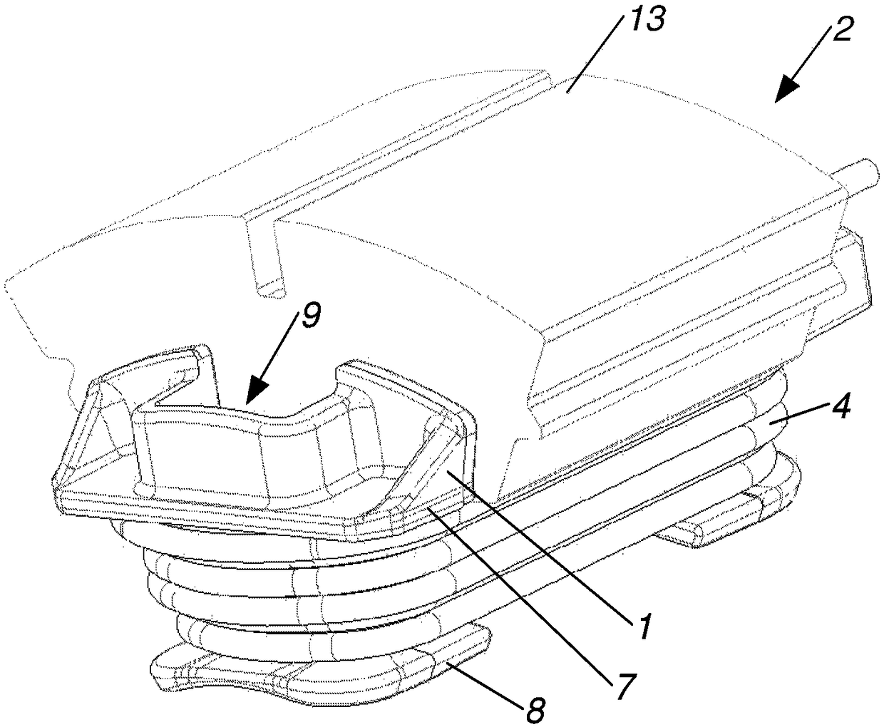
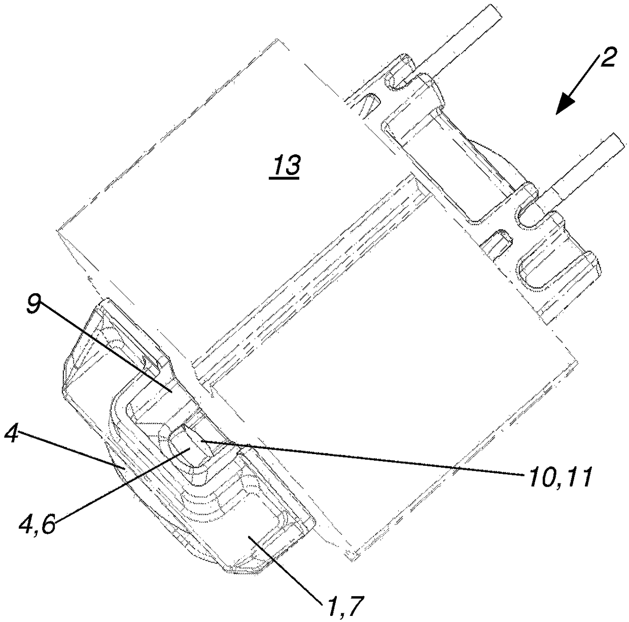
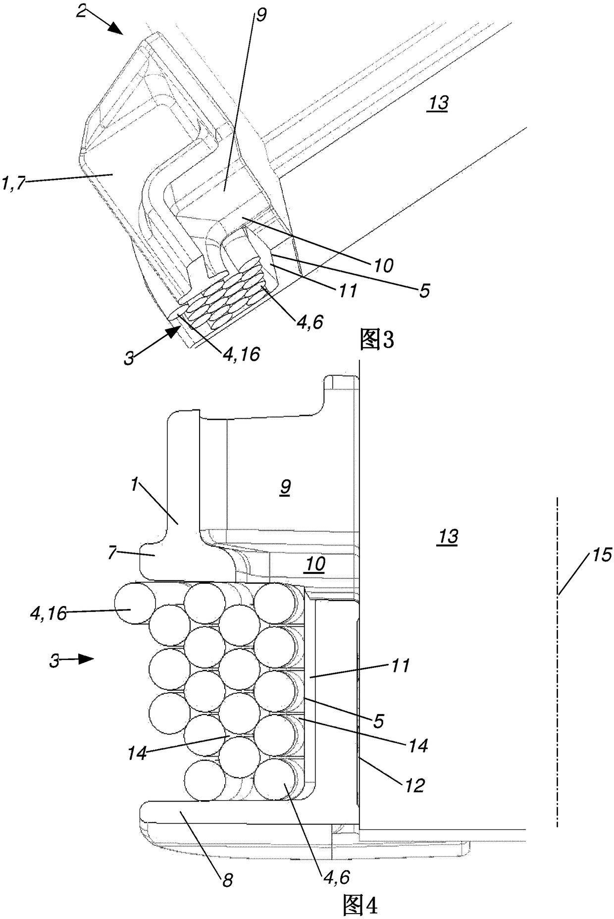
[0026] Figure 1 to Figure 8 Each shows an electrical coil arrangement 2 or a part of such a coil arrangement, which comprises at least one core 13 and at least one coil winding 4 which is wound around at least one region of the core 13 , wherein at the core 13 On at least one peripheral section, the coil carrier 1 is arranged between the core 13 and the coil winding 4 , wherein the coil carrier 1 has a winding receiving area 3 for at least one peripheral section of the coil winding 4 , the winding receiving area 3 Delimited by a winding receiving area inner surface 5 for contact with the innermost winding layer 6 of the coil winding 4 and at least one first end piece 7 protruding from the winding receiving area inner surface 5, wherein at the first end On the side of the component 7 facing away from the winding receiving area 3 is arranged an at least partially enclosed fluid receiving reservoir 9 , wherein the fluid receiving reservoir 9 is connected to the winding receiving...


PUM


Abstract

The invention relates to a coil former (1) for an electrical coil assembly (2), wherein the coil former (1) has a winding-holding region (3) for at least one peripheral segment of a coil winding (4),which winding-holding region (3) is bounded by a winding-holding region inner surface (5) for contact with an innermost winding layer (6) of the coil winding (4) and at least one first end piece (7) protruding from the winding-holding region inner surface (5). According to the invention, an at least partially surrounded fluid-holding reservoir (9) is arranged on a side of the first end piece (7) facing away from the winding-holding region (3), the fluid-holding reservoir (9) is connected to the winding-holding region (3) by a fluid passage opening (10), and the fluid passage opening (10) is arranged adjacent to the winding-holding region inner surface (5).

Description

technical field [0001] The invention relates to a coil holder according to the preamble of claim 1 . Background technique [0002] It is known that, in coils from the field of electrical technology, the actual coil winding is arranged on an insulating material part, which is referred to as a coil carrier. Such a coil carrier supports the winding process by helping, for example, to position the individual windings of the coil winding and to follow the desired shape of the coil more precisely. Furthermore, when the coil is arranged on a magnetic core or a simple core, the coil carrier at least partially electrically insulates the coil winding from the core and protects the core from mechanical loads when the coil winding is wound, mechanical loads It may cause deterioration of the magnetic properties of the core. [0003] Of course, cavities between the coil windings and the core or coil support can hardly be avoided. These cavities impair the heat transfer from the coil wi...

Claims


Application Information

Patent Timeline
Patent Type & Authority Applications(China)
IPC IPC(8): H01F5/02H01F27/32H01F41/12
CPCH01F5/06H01F27/28H01F27/32H01F27/40H01F41/00H02K15/12H01F5/02H01F27/325H01F27/327H01F41/127H01F27/06H01F27/10H01F41/06
Inventor 恩斯特·普兰德-施特里茨科
Owner EGSTON SYST ELECTRONICS EGGENBURG
Learn More