Scrap iron removing device

A technology of iron filings and installation rods, applied in the direction of magnetic separation, solid separation, chemical instruments and methods, etc., can solve the problems of being pressed under the material, insufficient iron removal, high labor intensity, etc., so as to facilitate adsorption removal and avoid The effect of manual scraping and simple structure

Active Publication Date: 2018-08-03
ZHENJIANG YUANDA TRANSMISSION MACHINERY
View PDF8 Cites 0 Cited by
  • Summary
  • Abstract
  • Description
  • Claims
  • Application Information

AI Technical Summary

Problems solved by technology

Adopting the conveyor belt conveying method has the following defects: iron filings are often pressed under the material, so some iron filings will not be absorbed, resulting in insufficient iron removal
In addition, when the existing iron remover is in use, it is generally scraped off the iron from the magnet by manual means, which has low efficiency and high labor intensity.

Method used


Image

  • Scrap iron removing device
  • Scrap iron removing device
  • Scrap iron removing device

Examples


Embodiment Construction

[0020] The present invention will be further described below in conjunction with the accompanying drawings.

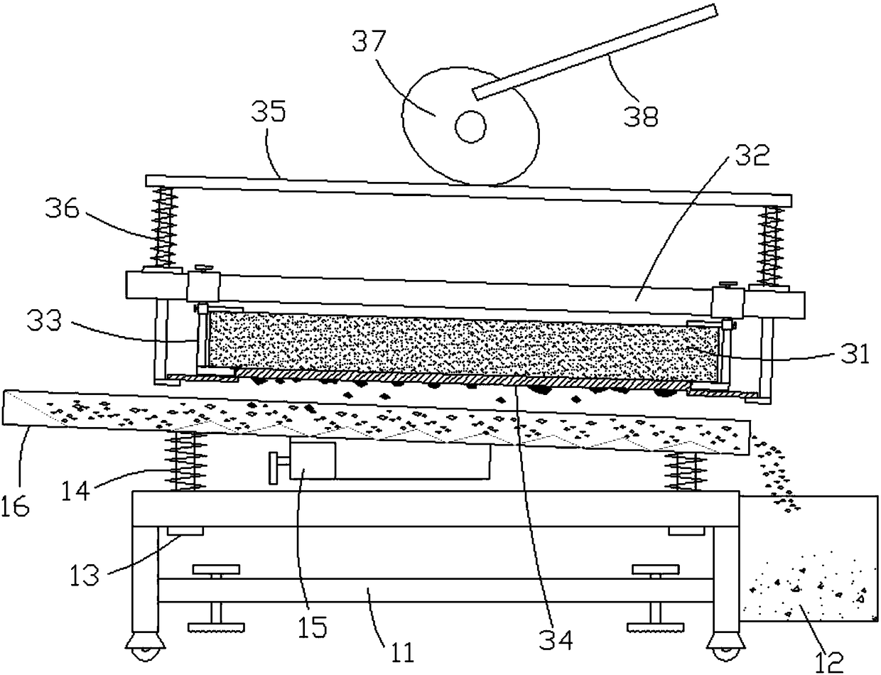
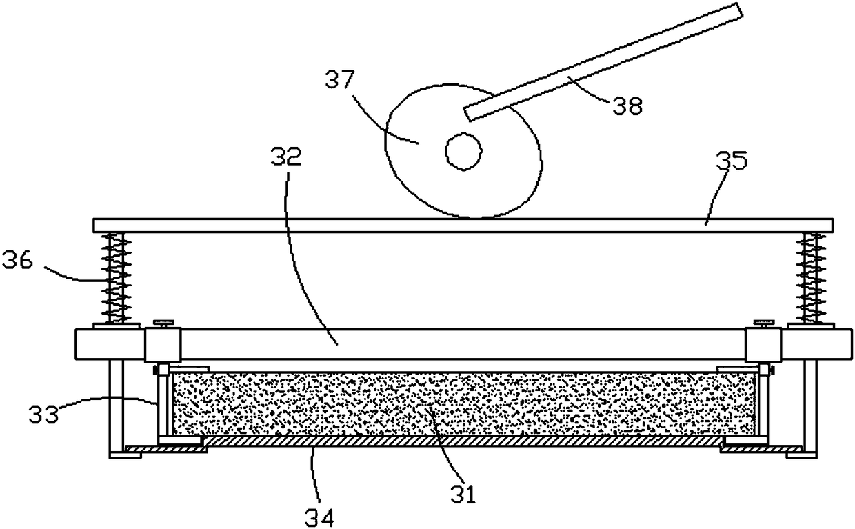
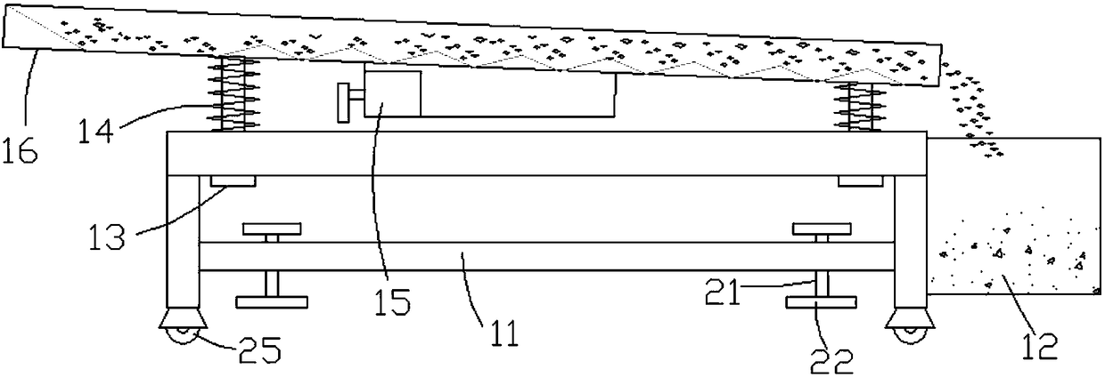
[0021] Such as Figure 1 to Figure 6 , a device for removing iron filings in the present invention, comprising a frame 11, a collection frame 12, a first guide rod 13, a first spring 14, a vibrating motor 15, a feeding trough 16, a permanent magnet 31, a mounting rod 32, a splint 33, Baffle plate 34, mounting bracket 35, second spring 36, cam 37 and handle 38, first guide rod 13 are plugged on the frame 11, and the top of first guide rod 13 is fixedly connected with feeding chute 16, and feeding chute 16 is obliquely arranged, and the discharge opening of feeding chute 16 is placed on the top of collecting frame 12, and collecting frame 12 is fixed on the frame 11. The first spring 14 is sleeved on the first guide rod 13 , and the upper and lower ends of the first spring 14 are in contact with the feeding chute 16 and the frame 11 respectively, and the vibration motor...


PUM


Abstract

The invention discloses a scrap iron removing device. According to the technical scheme, first guide rods are inserted into a machine frame, the top ends of the first guide rods are fixedly connectedwith a feeding tank, and a discharging port of the feeding tank is arranged above a collecting frame; first springs sleeve the first guide rods, and a vibration motor is fixedly connected to the lowerend face of the feeding tank; a mounting rod is arranged above the feeding tank, a permanent magnet is fixed on the mounting rod through two clamping plates, a mounting frame is inserted into the mounting rod, and second springs sleeve the mounting frame; and a baffle is fixedly connected to the bottom end of the mounting frame, the baffle abuts against the lower end face of the permanent magnet,a cam is arranged on the mounting frame, the circumferential surface of the cam abuts against the mounting frame, and a handle is fixed on the cam. According to the scrap iron removing device, the structure is simple, materials are jolted in the material conveying process, so that full attraction and removal of scrap iron are facilitated; and after the scrap iron is attracted, the mounting frameis pressed downwards, and the baffle is enabled to be far away from the permanent magnet so that the scrap iron can be discharged from the permanent magnet, manual scraping is avoided, and the use isconvenient.

Description

Technical field: [0001] The invention relates to a device for removing iron filings. Background technique: [0002] When the material is mixed with iron filings, it is often necessary to filter out the iron filings in the material. The existing method is generally to pour the material onto the conveyor belt, and then install an iron remover above the conveyor belt to realize the adsorption and removal of iron filings during the material transportation process. The conveyor belt conveying method has the following defects: iron filings are often pressed under the material, so some iron filings will not be absorbed, resulting in insufficient iron removal. In addition, when the existing iron remover is in use, the iron is generally scraped off the magnet by manual means, which has low efficiency and high labor intensity. Invention content: [0003] The present invention provides a device for removing iron filings in order to solve the above-mentioned problems in the prior ar...

Claims


Application Information

Patent Timeline
IPC IPC(8): B03C1/23
CPCB03C1/23
Inventor 马料宝马俊马成
Owner ZHENJIANG YUANDA TRANSMISSION MACHINERY
Why Eureka
Try Eureka