
Electronic clamp feeding device

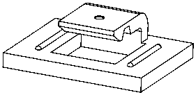
A feeding device and electronic clip technology, applied in the direction of transportation and packaging, conveyor objects, conveyors, etc., can solve the problems of large position deviation of electronic clips, unfavorable next process, and unfavorable processing overall equipment automation, etc., to achieve stable supply Ingenious effect of material and structure

Inactive Publication Date: 2018-08-03
胡贤娟
View PDF5 Cites 1 Cited by
  • Summary
  • Abstract
  • Description
  • Claims
  • Application Information

AI Technical Summary

Problems solved by technology

In current production, because electronic clip parts are small, electronic clip feeding is generally carried out manually, and a small number of advanced manufacturers use automatic feeding machines to directly supply to the next process, that is, sponge double-sided adhesive tape and release paper. pasting process, but it is difficult to adjust the feeding frequency in this way, which is not conducive to the next process
Moreover, the electronic clamp position deviation of the automatic feeder is large, which is not conducive to subsequent processing and overall equipment automation.

Method used


Image

  • Electronic clamp feeding device
  • Electronic clamp feeding device
  • Electronic clamp feeding device

Examples


Embodiment Construction

[0016] The present invention will be further described in detail below in conjunction with the accompanying drawings and examples. The following examples are explanations of the present invention and the present invention is not limited to the following examples.

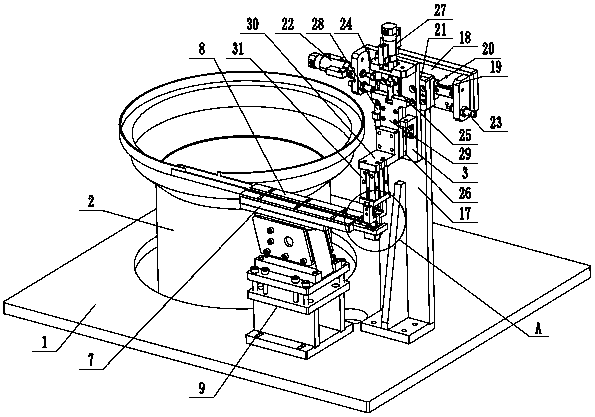
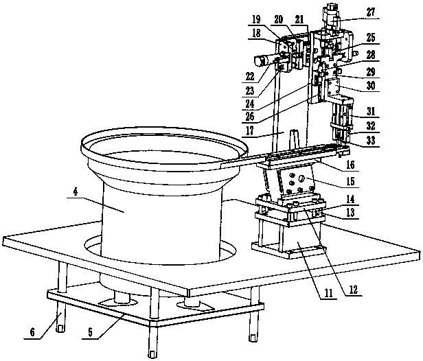
[0017] like figure 1 , figure 2 , image 3 and Figure 4Shown, a kind of electronic clip feeding device, it comprises frame bottom plate 1, vibrating feeding mechanism 2, electronic clip grasping mechanism 3, described vibrating feeding mechanism 2 comprises vibrating feeding machine 4, feeding machine mounting plate 5. Connecting screw 6, linear vibrating trough 7, electronic clamping plate 8, vibrating trough support assembly 9, fixed trough 10, the feeder mounting plate 5 is connected with the frame bottom plate 1 through the connecting screw 6, and the The vibration feeder 4 is installed on the feeder mounting plate 5, and the linear vibration feeder 7 is installed on the vibration feeder support assembly 9,...


PUM


Abstract

The invention provides an electronic clamp feeding device, and belongs to the technical field of electronic accessories. The electronic clamp feeding device comprises a machine frame bottom plate, a vibration feeding mechanism and an electronic clamp grabbing mechanism; a linear vibration material groove of the vibration feeding mechanism is installed on a vibration material groove supporting assembly, the left end of the linear vibration material groove is connected to a vibration feeding machine, and an electronic clamp pressing plate is installed on the two sides of the upper end of the linear vibration material groove; a linear vibration adjusting plate of the vibration material groove supporting assembly is installed on an I-shaped supporting base through connecting screws of the adjusting plate, and the linear vibration adjusting plate is further in threaded connection with vibration limiting screws; and a fixed material groove is formed in the right end of the linear vibration material groove, the electronic clamp grabbing mechanism is arranged on one side of the fixed material groove, and a grabbing clamping finger air cylinder of the electronic clamp grabbing mechanism isconnected to a grabbing first clamping finger and a grabbing second clamping finger. According to the electronic clamp feeding device, electronic clamps can be automatically and stably fed one by one,the electronic clamps are small in position deviation, structure is reasonable and compact, reliability is good, and the automation degree is high.

Description

technical field [0001] The invention relates to the technical field of electronic accessories, in particular to an electronic clip feeding device. Background technique [0002] The use of electronic components is huge, and each integrated circuit needs to use many electronic components. Therefore, the production scale of electronic components is very large. Electronic components are the basis of electronic products. Commonly used electronic components include: resistors, capacitors, inductors, potentiometers, transformers, etc. Mounting electronic clip is an accessory that can quickly paste and install electronic components, and has great application value in the field of electronic equipment. In the production process of attaching electronic clips, it is first necessary to paste sponge double-sided adhesive tape and release paper on the back of the plastic electronic clip, then apply cleaning agent and put it into a plastic bag, and then seal the transparent tape on the p...

Claims


Application Information

Patent Timeline
Patent Type & Authority Applications(China)
IPC IPC(8): B65G27/02B65G47/90
CPCB65G27/02B65G47/901B65G47/905
Inventor 胡贤娟
Owner 胡贤娟
Learn More