
Structure of warm mixing recycling agent

A technology of warm-mixing regenerant and regenerant, which is applied to building components, building structures, building insulation materials, etc., can solve the problems of difficult to control the dosage and inconvenient transportation of regenerant, and achieve improved water stability, flexibility and Viscosity effect

Active Publication Date: 2018-08-03
CHONGQING JIAOTONG UNIVERSITY
View PDF6 Cites 2 Cited by
  • Summary
  • Abstract
  • Description
  • Claims
  • Application Information

AI Technical Summary

Problems solved by technology

[0004] The purpose of the present invention is to provide a structure of warm-mixing regenerant to solve the problem that the regenerant is not easy to transport and difficult to control the dosage during use

Method used

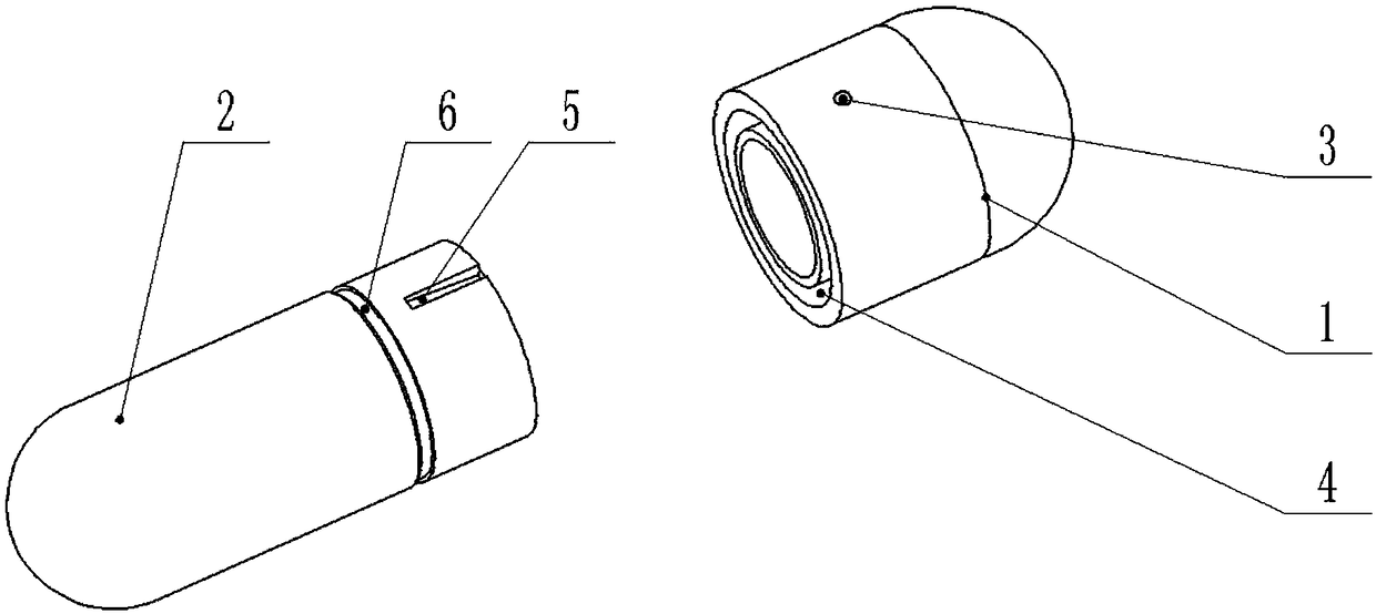
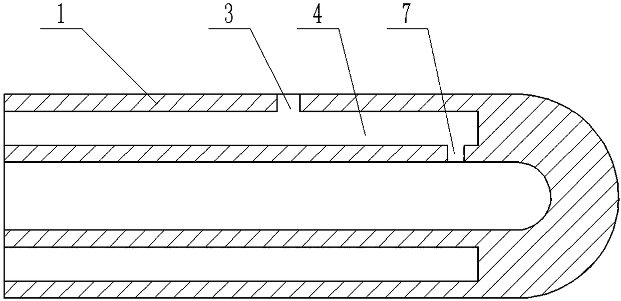
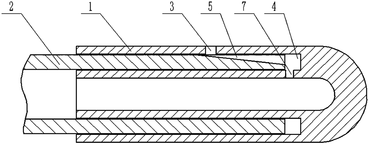

Image

  • Structure of warm mixing recycling agent
  • Structure of warm mixing recycling agent
  • Structure of warm mixing recycling agent

Examples


Embodiment 1

[0030] Such as figure 1As shown, this embodiment is a structure of a warm-mixing regenerant, including a regenerant and a capsule shell. The quality of the components in the regenerant is: 2kg of waste engine oil, 0.05kg of graphene, 2kg of light oil, 0.5kg of glycerol lipids, and 0.9kg of desulfurized rubber powder. The mass of the components of the capsule shell is: fiber 0.1kg, polyene material 0.3kg, devulcanized rubber powder 0.3kg. The capsule shell includes a shell cap 1, a shell 2 and an encapsulating ring. Such as figure 2 , image 3 The left end of the shown shell cap 1 is circumferentially provided with an annular insertion groove 4, and the right bottom of the insertion groove 4 is provided with a flow channel 7, the flow channel 7 is 1 cm away from the right end of the insertion groove 4, and the shell cap 1 is provided with a pouring port 3, The filling port 3 communicates with the insertion groove 4 . The right end of the casing 2 is provided with a draina...

Embodiment 2

[0037] The difference from Example 1 is that the proportioning ratio of the warm-mix regenerant is different, specifically, the quality of the regenerant components is: 5 kg of waste engine oil, 0.5 kg of graphene, 3.5 kg of light oil, 1.5 kg of glycerol lipids, Desulfurized rubber powder 1.35kg. The mass of the components of the capsule shell is: 0.2kg of fiber, 0.5kg of polyene material, and 0.45kg of devulcanized rubber powder.

Embodiment 3

[0039] The difference from Example 1 is that the proportioning ratio of the warm-mix regenerant is different, specifically, the quality of the regenerant components is: 3.5kg of waste engine oil, 0.3kg of graphene, 3.3kg of light oil, 1kg of glycerol lipids, Desulfurized rubber powder 1kg. The mass of the components in the capsule shell is: fiber 0.11kg, polyene material 0.46kg, desulfurized rubber powder 0.33kg.


PUM


Abstract

The invention belongs to the technical field of asphalt recycling agents and in particular discloses a structure of a warm mixing recycling agent. The structure comprises a capsule shell, and a recycling agent composed of used oil, graphene, light oil and desulfurized rubber powder, wherein the recycling agent is liquid and is filled in the capsule shell; the capsule shell comprises a shell cap, ashell and an encapsulation ring; the shell is matched with the shell cap; the encapsulation ring is used for sealing the joint of the shell cap and the shell; an insertion groove through which the shell is inserted is formed in the end of an opening in the shell cap; the insertion groove is in interference fit with the shell; a rubber is arranged at the end, which is far away from the shell, of the insertion groove; the runner is communicated with the interior of the shell cap; a filling port is formed in the shell cap and communicated with the insertion groove; a drainage groove is formed inthe end, which is close to the shell cap, of the shell; the drainage groove is communicated with the insertion groove; the material of the encapsulation ring is the same as that of the shell cap andthe shell. The invention aims to solve the problems that the recycling agent is difficult to transport and the usage amount is difficultly controlled during use.

Description

technical field [0001] The invention belongs to the technical field of asphalt regenerant, and specifically discloses the structure of a warm-mix regenerant. Background technique [0002] Most of the high-grade highways in my country are mainly based on asphalt pavement. According to the design service life of 15 or 20 years, most of the asphalt pavement in China has entered the peak period of maintenance and maintenance, and frequent maintenance and overhaul maintenance. At present, the commonly used maintenance methods are to mill the old asphalt pavement and re-pave the fresh asphalt mixture, or use the recycling technology to reuse the waste asphalt mixture, and use the recycled asphalt mixture for the middle and lower layers of the asphalt pavement. Recycling waste asphalt pavement is an efficient and environmentally friendly construction waste recycling technology. Although the road performance of waste asphalt mixture does not meet the specification requirements, afte...

Claims


Application Information

Patent Timeline
Patent Type & Authority Applications(China)
IPC IPC(8): C08L95/00C08L21/00C08L101/00C08L91/00C08K3/04B65D25/00
CPCB65D25/00C08L95/00C08L2201/08C08L2205/035C08L21/00C08L101/00C08L91/00C08K3/042Y02A30/30Y02W30/91
Inventor 周刚
Owner CHONGQING JIAOTONG UNIVERSITY
Learn More