Mortise-tenon connection structure of fabricated beam-column joints

A technology of beam-column joints and connection structures, which is applied in the direction of building construction and construction, can solve the problems of less application of concrete structures, complex stress, and more construction conditions, so as to reduce the use of workers and related equipment and improve Durability and long-term performance, the effect of reducing the use of formwork

Active Publication Date: 2018-08-03
TAIYUAN UNIV OF TECH
View PDF4 Cites 7 Cited by
  • Summary
  • Abstract
  • Description
  • Claims
  • Application Information

AI Technical Summary

Problems solved by technology

[0004] At present, the node connection of prefabricated structures is mainly divided into wet connection and dry connection. Wet connection requires secondary pouring of nodes. The pouring process involves concrete mixing, use of formwork, maintenance of newly poured concrete and newly poured concrete. A series of problems such as strength testing, complex construction procedures, cumbersome operations, and more requirements for construction conditions have seriously affected the progress of the project and caused construction pollution. It does not meet the applicable, economical, safe, green, and beautiful prefabricated building services. Development methods
[0005] There are also many problems in the existing dry connection method. The existing dry connection mostly uses bolts, welds and other connection methods. Although the related effects of secondary pouring are avoided, the connection methods of bolts and welds It is used in steel structure and less used in concrete structure
Moreover, the connection methods such as bolts and welding also have many disadvantages, such as the force is more complicated, and the section is weakened to a certain extent, etc.
[0006] In view of the above-mentioned problems existing in the traditional prefabricated structure, it is urgent to provide a new construction structure and construction method, which is convenient for construction and easy to assemble. disadvantages

Method used


Image

  • Mortise-tenon connection structure of fabricated beam-column joints
  • Mortise-tenon connection structure of fabricated beam-column joints
  • Mortise-tenon connection structure of fabricated beam-column joints

Examples


Embodiment Construction

[0043]In order to make the invention's technical means, creative features, goals and effects easy to understand, the present invention will be further elaborated below in conjunction with specific illustrations.

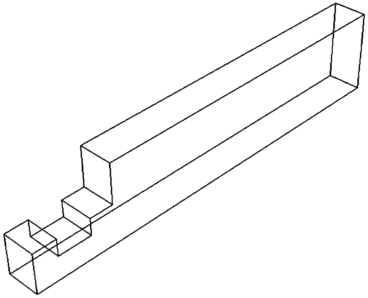
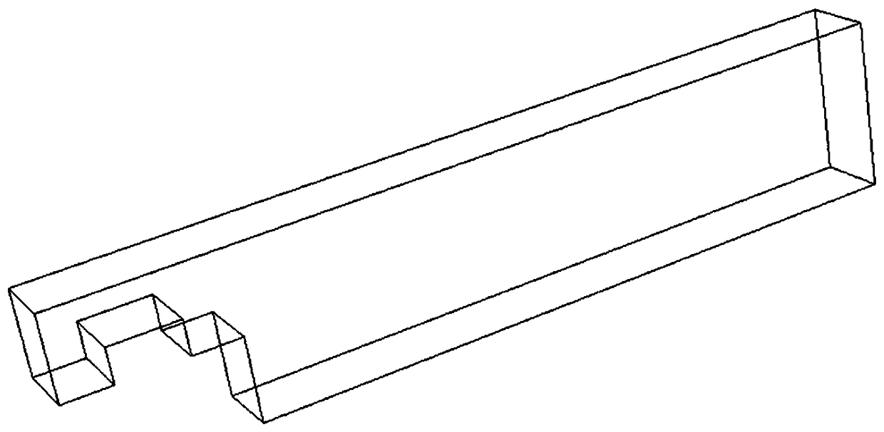
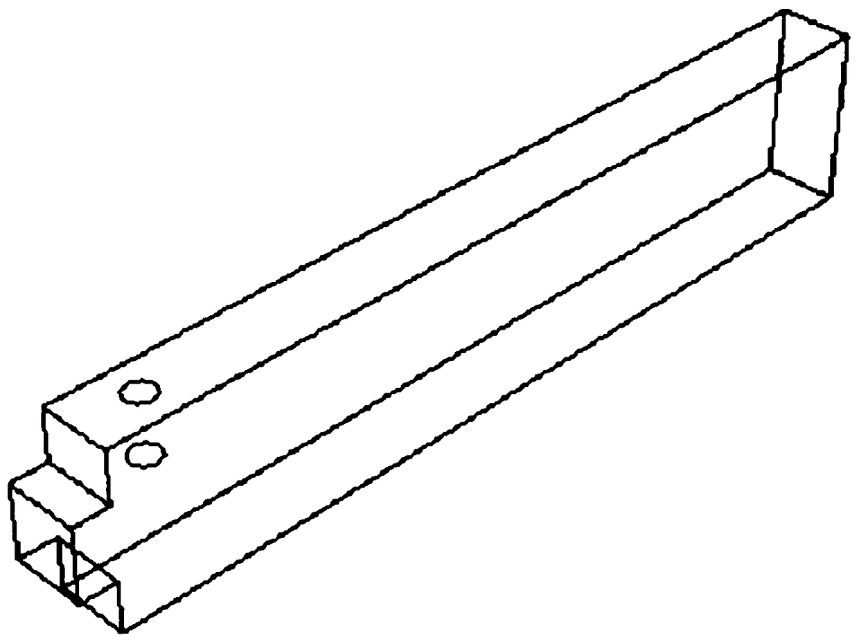
[0044] like figure 1 , 2 The schematic diagrams of the first beam and the second beam are respectively. One end of the two beams extends outward to form a tenon, and the tenons of the two beams have a symmetrical structure, so that after the butt joint, a middle width direction can be formed for installation. The tongue and groove of the stringer. image 3 It is a schematic diagram of the longitudinal beam structure. The round hole in the figure indicates the reserved tenon groove on the longitudinal beam. The tenon groove is located next to the tenon and will not be inserted into the tenon groove of the beam, so that the tenon of the upper column can be inserted. Figure 4 It is a bottom view of the bottom of the upper column. The four rectangles at the four corne...


PUM


Abstract

The invention provides a mortise-tenon connection structure of fabricated beam-column joints. The connection mode comprehensively considers the connection between upper columns and lower columns and the connection between beams and columns. Reserved chase mortises are formed in the upper columns, the lower columns, cross beams and longitudinal beams. During construction, secondary joint pouring for fabricated wet process connection is avoided, and the use of bolts and welding joints for dry-type joint connection is avoided. During construction, a traditional method is changed, the beams and columns are spliced through the reserved tenons and chase mortises of the beams and the columns, and the structure is assembled and formed at a time by pouring fine stone concrete into small holes and other processes. The mechanical properties of the joints is ensured, at the same time, the environmental pollution caused by the secondary pouring is avoided, the construction efficiency is improved, and the mortise-tenon connection structure of the fabricated beam-column joints is quite suitable for the development prospects of the fabricated type.

Description

technical field [0001] The invention relates to the field of industrial and civil buildings, in particular to an assembled beam-column joint mortise and tenon connection structure. Background technique [0002] Assembled architecture began to arouse people's interest in the beginning of the 20th century, and finally realized to the sixties. Because the construction speed of prefabricated building is fast, and production cost is relatively low, promotes rapidly all over the world. In accordance with the requirements of promoting supply-side structural reform and new urbanization development, vigorously develop prefabricated buildings such as steel structures and concrete, which has multiple effects such as developing new energy-saving and environmental protection industries, improving building safety levels, and promoting the resolution of excess capacity. [0003] Today, China is still a large agricultural country, with nearly 60% of the land in the countryside and about th...

Claims


Application Information

Patent Timeline
Patent Type & Authority Applications(China)
IPC IPC(8): E04B1/21
CPCE04B1/21
Inventor 刘元珍宋佳雨张家广张玉郝潞岑
Owner TAIYUAN UNIV OF TECH
Why Eureka
Try Eureka