Double-motor driving structure of double-rotor type compressor and control method of double-motor driving structure

A dual-motor drive and compressor technology, applied in the field of compressors, can solve the problems of pollution, reduce the life and performance of the stack, and stack poisoning, and achieve the effects of avoiding oil leakage, improving accuracy and reducing contact force.

Pending Publication Date: 2018-08-03
NINGBO BAOSI ENERGY EQUIP
View PDF5 Cites 1 Cited by
  • Summary
  • Abstract
  • Description
  • Claims
  • Application Information

AI Technical Summary

Problems solved by technology

Traditional compressors of this type rely on a single motor with synchronous gears for dual-shaft drive, but because the synchronous gear structure of this type of compressor requires a large amount of lubricating oil, when the compressor is compressing high-clean working fluid, the lubricating oil will Enter the working chamber through the gap between the shaft and the cylinder, causing contamination that is unacceptable for the high-purity environment required by the compressor, for example, when this type of compressor is used in a hydrogen fuel cell system Pollution can cause stack poisoning, which will greatly reduce the life and performance of the stack

Method used


Image

  • Double-motor driving structure of double-rotor type compressor and control method of double-motor driving structure
  • Double-motor driving structure of double-rotor type compressor and control method of double-motor driving structure
  • Double-motor driving structure of double-rotor type compressor and control method of double-motor driving structure

Examples


Embodiment Construction

[0026] The present invention will be described in further detail below in conjunction with the accompanying drawings.

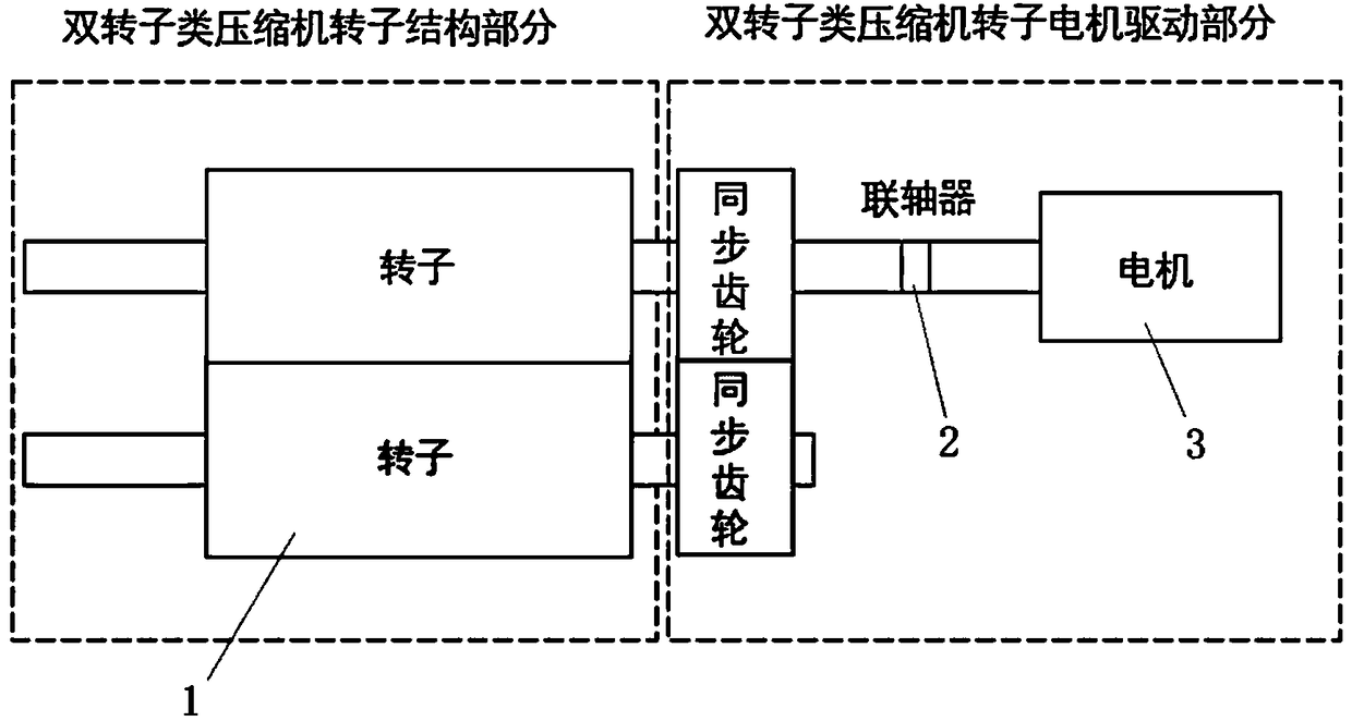
[0027] see figure 1 , the present invention can be modified on the basis of the traditional double-rotor compressor driving structure. In the original driving structure, the motor is connected to a certain rotor, and the other rotor is driven by synchronous gears. This driving method increases oil pollution.

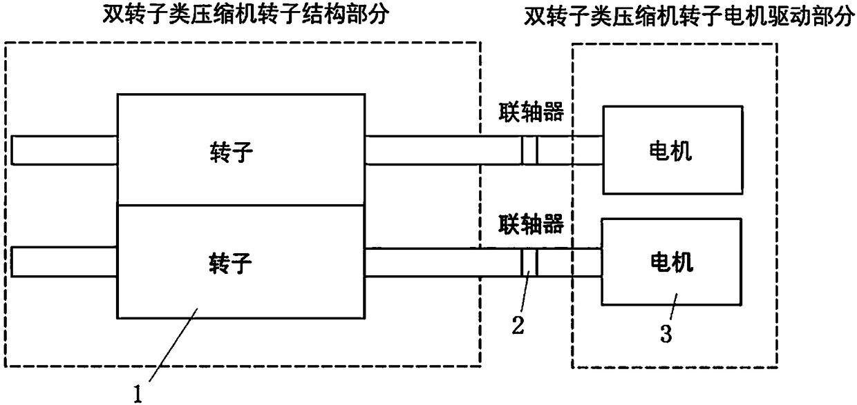
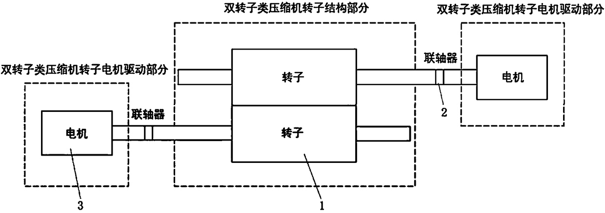
[0028] see Figure 2-3 , the present invention adopts a double-motor drive structure, two motors 3 are respectively connected to two compressor rotors 1 through a coupling 2, and the two motors 3 are arranged on the same side of the two compressor rotors 1 in a row-by-row manner or adopt a fork Arranged in rows on opposite sides of the two compressor rotors 1, synchronous gears are omitted, thereby avoiding the problem of oil leakage.

[0029] see Figure 4-8 , the control method of double-motor drive structure of the present invention, comprises the...


PUM


Abstract

The invention discloses a double-motor driving structure of a double-rotor type compressor and a control method of the double-motor driving structure. The double-motor driving structure comprises twomotors which are correspondingly connected with two compressor rotors through couplers, the two motors are connected with a power supply, and the speed ratio of the two motors is controllable. The control method is divided into three control schemes according to the speed ratio control precision requirement of the compressor rotors, and the control method comprises the two motors directly connected with one power supply, wherein one motor is connected with the power supply through a frequency converter, and the two motors are correspondingly connected with the power supply through the frequency converter; and the frequency converter is provided with a controller, and the controller is used for analyzing the difference value between the speed ratio of two rotation speed sensors and the setspeed ratio; and the set frequency of the frequency converter is adjusted, the rotating speed of the motors connected with the frequency converter is controlled, and the constant speed ratio of the two motors is kept. According to the double-motor driving structure of the double-rotor type compressor and the control method of the double-motor driving structure, the normal operation of the rotor type compressor is ensured, synchronous gears required by a traditional structure is omitted, so that the problem of oil leakage is avoided, and the double-motor driving structure is symmetrical and hasthe effects of reducing noise and the like.

Description

technical field [0001] The invention relates to compressor technology, in particular to a dual-motor drive structure of a dual-rotor compressor and a control method thereof. Background technique [0002] Twin-rotor compressors are a type of positive displacement compressors, including twin-screw, Roots and claw compressors. Double-rotor compressors are widely used in various industrial occasions due to their long mechanical life, forced suction and exhaust, no wearing parts, reliable operation, small vibration, low noise, stable operation, and no surge phenomenon. The common structural feature of this type of compressor is that there are two rotating shafts at the same time and the two rotating shafts move at a certain speed ratio. Traditional compressors of this type rely on a single motor with synchronous gears for dual-shaft drive, but because the synchronous gear structure of this type of compressor requires a large amount of lubricating oil, when the compressor is comp...

Claims


Application Information

Patent Timeline
Patent Type & Authority Applications(China)
IPC IPC(8): F04C18/12F04C29/00F04C28/08F04C28/28
CPCF04C18/12F04C28/08F04C28/28F04C29/00
Inventor 何志龙李丹童邢子文姬蓝天杨显照
Owner NINGBO BAOSI ENERGY EQUIP
Why Eureka
Try Eureka