OFDMA technology based visible light indoor positioning method

An indoor positioning and visible light technology, applied in the field of visible light indoor positioning based on OFDMA technology, can solve problems such as affecting positioning quality and degrading communication quality, and achieve the effects of high data transmission rate, high signal-to-noise ratio, and good anti-fading performance.

Inactive Publication Date: 2018-08-03
SOUTH CHINA UNIV OF TECH
View PDF6 Cites 10 Cited by
  • Summary
  • Abstract
  • Description
  • Claims
  • Application Information

AI Technical Summary

Problems solved by technology

However, most systems based on wireless communication are affected by electromagnetic interference, and the communication quality degrades in the case of sharing by multiple users, which directly affects the positioning quality

Method used


Image

  • OFDMA technology based visible light indoor positioning method
  • OFDMA technology based visible light indoor positioning method
  • OFDMA technology based visible light indoor positioning method

Examples


Embodiment 1

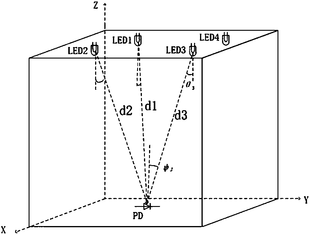
[0044] Such as figure 1 Shown is a schematic diagram of visible light indoor positioning based on OFDMA technology. Install M LED lamps on the ceiling according to the needs of the indoor environment, where M≥3, and every three adjacent LED lamps are a group of positioning units.

[0045] A visible light indoor positioning method based on OFDMA technology, specifically comprising:

[0046] S1. Encode the coordinate information of each LED lamp into the ID code of the corresponding LED lamp, so that each LED lamp has a unique ID code;

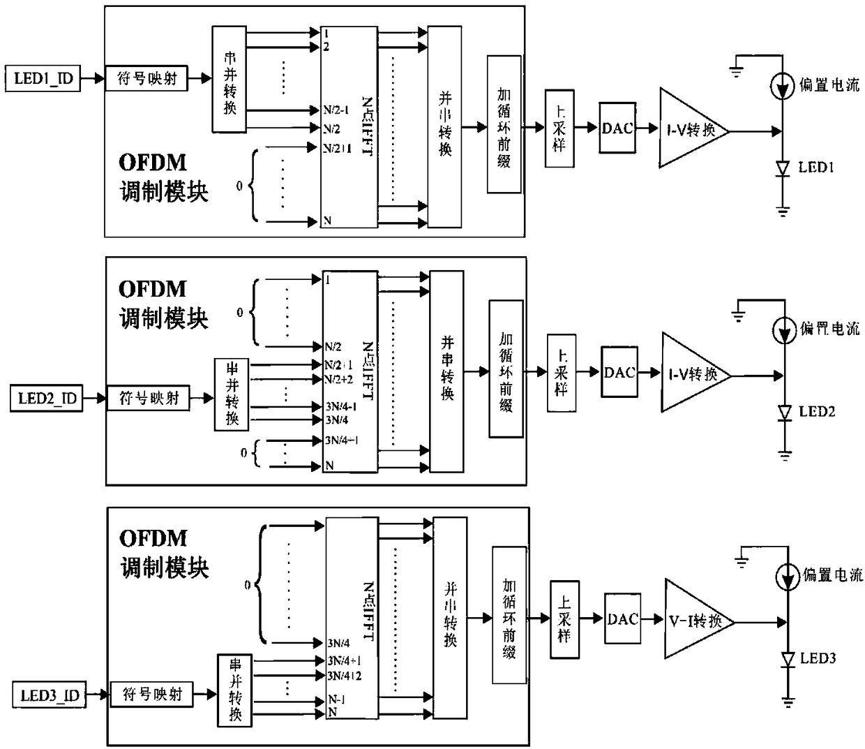
[0047] S2. Divide every three LED lamps into one group, and perform OFDM modulation on the ID codes of the three LED lamps in each group through the OFDM modulation module, and the OFDM symbols generated after modulation are converted into analog quantities through a digital-to-analog conversion circuit. Then load it to the LED lamp to emit light signal through the LED drive circuit;

[0048] Such as figure 2 Shown is a flow chart of three LE...

Embodiment 2

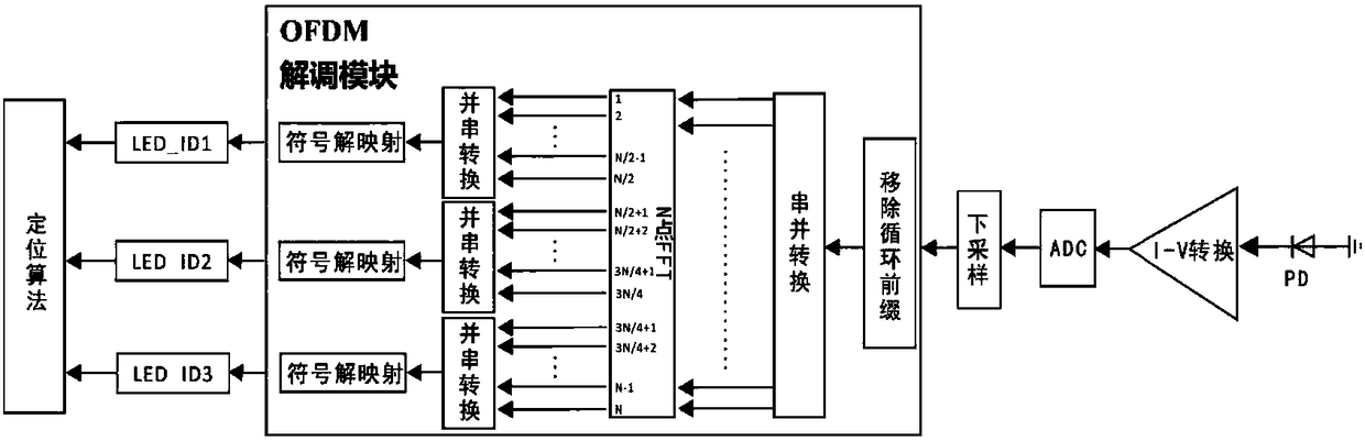
[0055] Through MATLAB simulation based on the principle of OFDMA, the ID signals of the three LED lamps are transmitted in the three-part orthogonal sub-channels in the 256-point OFDM modulation system, in which the ID information of LED1 occupies subcarriers 1 to 128, and the remaining unoccupied subcarriers The signal on LED2 is filled with zeros; the ID information of LED2 occupies subcarriers 129-192, and the signals on the remaining unoccupied subcarriers are zero-filled; the ID information of LED3 occupies subcarriers 193-256, and the remaining unoccupied subcarriers The signal above is zero-filled. Due to the orthogonality of the channel, the ID information of the corresponding LED lamp in the mixed signal can be demodulated at the receiving end. The channel uses additive Gaussian white noise as noise interference, uses wavelet filtering to denoise, and establishes an indoor space with a unit of 2m×2m×3m, in which LED lamps are located at the endpoints of the unit. Sin...


PUM


Abstract

The invention discloses an OFDMA technology based visible light indoor positioning method. The method comprises steps that sending ends of three LED lamps are distributed with three ID signals respectively, an OFDM modulation module carries out OFDM modulation on the three ID signals in the same modulation index, and three modulated ID signals are transmitted in sub-channels orthogonal with one another. After being received by each mobile terminal, the signals are amplified and undergo noise filtering by the reception circuit and then are then input to an OFDM demodulation module, and the OFDMdemodulation module obtains the ID signals sent by the three LED lamps by demodulation. According to received ID information of optical signals of the LED lamps and attenuation of the signals, the mobile terminals can be located accurately via a triangular positioning algorithm. Visible light communication is used, application for the frequency spectrum is not needed in the visible light band, and a present commercial LED lamp light source is used to satisfy illumination as well as positioning and communication. The method also has the advantages of low hardware cost, high positioning precision, free of electromagnetic radiation, green and safe.

Description

technical field [0001] The present invention relates to the field of visible light communication, in particular to a visible light indoor positioning method based on OFDMA technology. Background technique [0002] In the era of mobile Internet, various location-based location service systems are becoming more and more common. At present, the most widely used outdoor radio positioning system is the GPS global positioning system of the United States, and the civilian-level positioning accuracy can reach within 15 meters. However, in indoor environments such as home offices and large shopping malls where people's activities are frequent, as well as special environments such as tunnels and low parking lots, traditional satellite positioning systems such as GPS are difficult to use due to the shielding effect of radio signals. In the past 10 years, many indoor positioning schemes have been proposed based on radio wave technology. Mainly include: WLAN, RFID, UWB, WIFI, ultrasoun...

Claims


Application Information

Patent Timeline
Patent Type & Authority Applications(China)
IPC IPC(8): G01S5/16
Inventor 耿魁伟彭振敬朱嘉祺姚若河黄华茂
Owner SOUTH CHINA UNIV OF TECH
Why Eureka
Try Eureka