
Method for analyzing regenerative heating furnace flow field and internal temperature and thermal stress of workpiece

An analysis method and heating furnace technology, applied in the field of heat treatment, can solve the problems of not considering the thermal process of the heating furnace, not studying the numerical simulation dynamic analysis and calculation of the regenerative heating furnace, etc., to achieve the effect of simple modeling process and accurate results

Inactive Publication Date: 2018-08-03
YANSHAN UNIV
View PDF2 Cites 21 Cited by
  • Summary
  • Abstract
  • Description
  • Claims
  • Application Information

AI Technical Summary

Problems solved by technology

At present, most scholars only dynamically analyze the thermal process in a regenerative heating furnace during the reversing process or under cold conditions, or simulate the thermal process simulation analysis in which only one tube blank is heated, and do not consider the actual production of the heating furnace. The thermal process after dynamic continuous reversing when multiple tube blanks are heated at the same time, there is no research on the numerical simulation dynamic analysis and calculation of regenerative heating furnace

Method used


Image

  • Method for analyzing regenerative heating furnace flow field and internal temperature and thermal stress of workpiece
  • Method for analyzing regenerative heating furnace flow field and internal temperature and thermal stress of workpiece
  • Method for analyzing regenerative heating furnace flow field and internal temperature and thermal stress of workpiece

Examples


Embodiment Construction

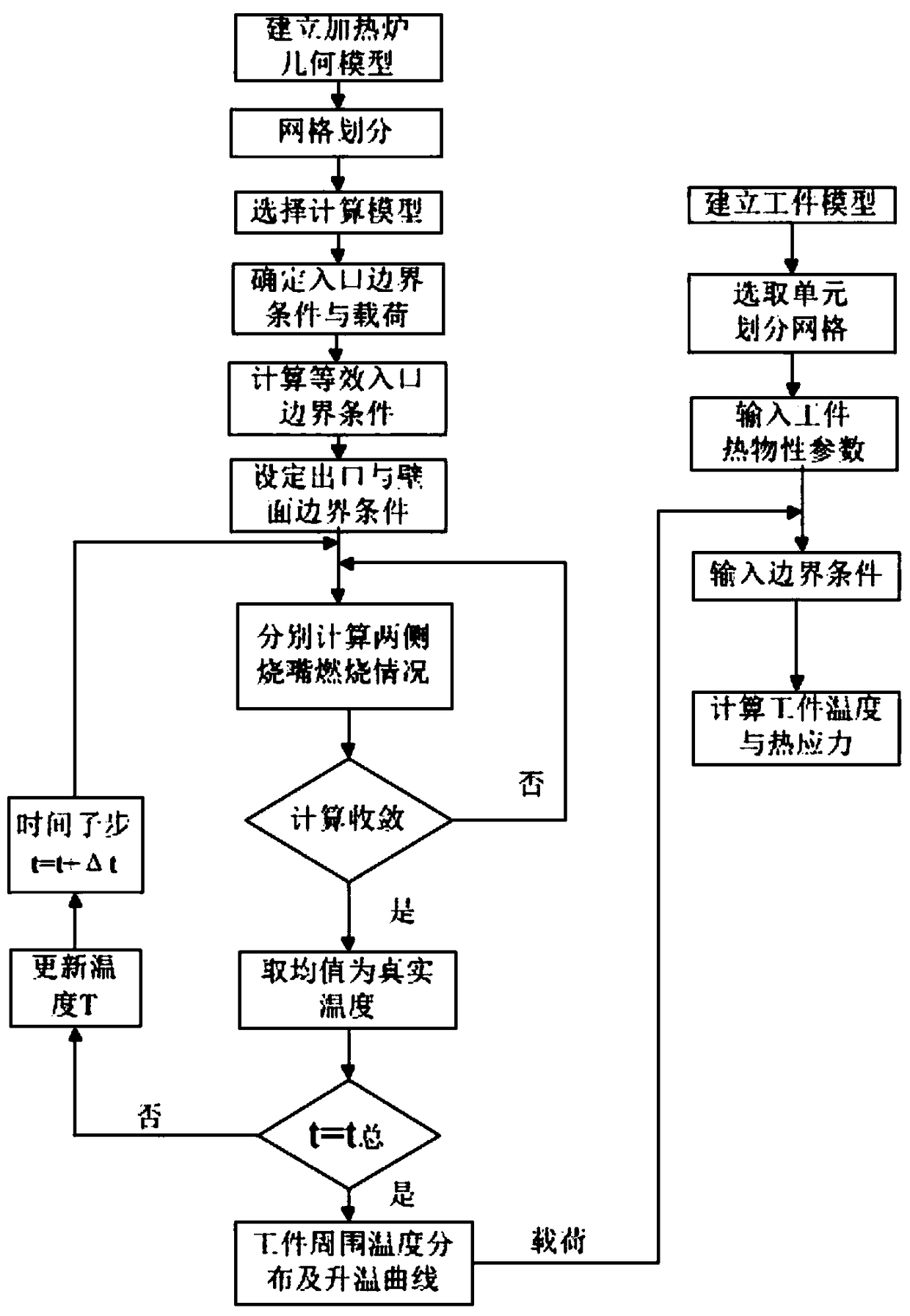
[0030] figure 1 Shown invention process figure, specific embodiment is as follows:

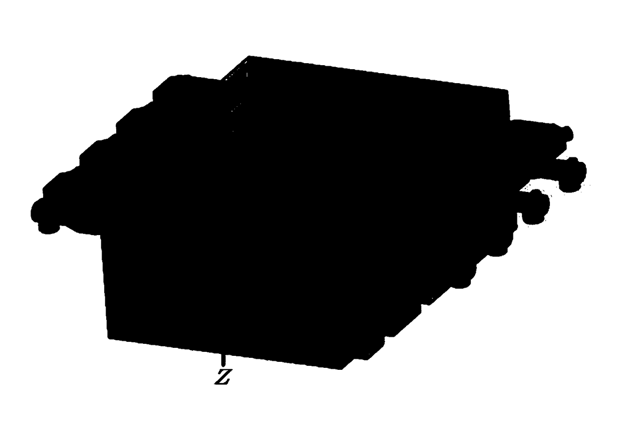
[0031] Step a) Use the 3D software SolidWorks to establish a geometric model including the main body of the heating furnace, air burners, gas burners, workpieces, and workpiece supports according to the measured dimensions on site. figure 2 shown;

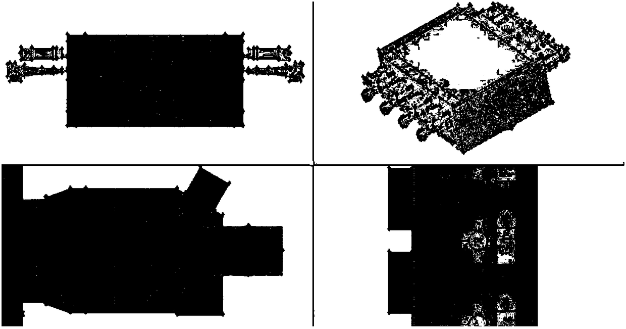
[0032] Step b) Dividing the grid, adopting a combination of structured grid division and unstructured grid division, and performing grid refinement on key parts such as the surroundings of the workpiece and the burner in the furnace, and the structural grid using Gambit The Map method is used for division, and the unstructured grid is divided by TGfid method, and the number of model grids finally obtained is 4,648,860;

[0033] Step c) Select the numerical simulation calculation model, in which the k-ε model is selected for the turbulence calculation model, the Species-Transport combustion model is used for the combustion calculation model, and ...


PUM


Abstract

A method for analyzing a regenerative heating furnace flow field and an internal temperature and a thermal stress of a workpiece is characterized in that the content of the method specifically comprises the following steps of (a) establishing a regenerative heating furnace geometrical model; (b) dividing a grid; (c) selecting a numerical simulation calculation model; (d) determining an entrance boundary condition, setting a model entrance condition as a speed entrance condition; (e) setting exit and wall boundary conditions; (f) respectively calculating a respective burning temperature field of burner nozzles at two sides of the heating furnace in a reversing process; (g) establishing a furnace internal processing workpiece model; (h) selecting a thermal-structural analysis unit to performgrid division on the furnace internal processing workpiece model; (i) inputting a thermophysical parameter of the furnace internal processing workpiece model; and (j) distributing the temperature field in the heating furnace into foundation and boundary conditions, and performing computational analysis on a furnace internal processing workpiece. According to the method for analyzing the regenerative heating furnace flow field and the internal temperature and the thermal stress of the workpiece, a modeling process is simple and a result is more accurate; model parameters can be adjusted according to the difference of the hating furnace and the workpiece; and the method is adapted widely.

Description

technical field [0001] The invention relates to the field of heat treatment, in particular to a method for analyzing the flow field of a regenerative heating furnace, internal workpiece temperature and thermal stress based on FLUENT and ANSYS simulation platforms. Background technique [0002] At present, many workpieces require a heating process before deformation treatment, and this heating process, as an important heat treatment link in the entire production process, has a crucial impact on the thermoplasticity and grain quality of the workpiece. Among them, the regenerative heating furnace adopts the heating method of single regenerative combustion heating, adopts an independently set regenerator or regenerative burner, which can heat air or gas, adopts regenerative high-temperature air combustion technology, and passes through the gas Fuel or combustion-supporting air and flue gas alternately pass through the heat storage body to realize extreme waste heat recovery and ...

Claims


Application Information

Patent Timeline
IPC IPC(8): G06F17/50
CPCG06F30/23G06F2119/06G06F2119/08
Inventor 刘丰冉鑫
Owner YANSHAN UNIV
Learn More