Constant-flow device

A current, voltage-to-current technology, applied in output power conversion devices, conversion of DC power input to DC power output, instruments, etc., can solve problems such as efficiency reduction, and achieve the effect of improving overall efficiency, saving external space and cost

Active Publication Date: 2018-08-03
深圳市群芯科创电子有限公司
View PDF6 Cites 3 Cited by
  • Summary
  • Abstract
  • Description
  • Claims
  • Application Information

AI Technical Summary

Problems solved by technology

[0002] With the rapid popularization of large-screen smartphones, the requirements for battery capacity are getting higher and higher, and the corresponding charging speed is also required to be faster and faster. Now the typical fast charging field is QC3.0, QC4.0; QC4.0 The charging power reaches nearly 30W, and the output current of the five-volt output gear can reach 6A. The current most popular QC3.0 and QC4.0 charging circuits mostly use the constant current on the secondary side of the transformer, and set the constant current sampling resistor. The sampling resistor must be at least 10mΩ, and the loss of at least 0.36W on the sampling resistor will reduce the efficiency of the entire system by 1.5%.

Method used


Image

  • Constant-flow device

Examples


Embodiment 1

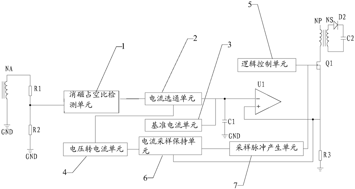
[0032] Please refer to figure 1 , Embodiment 1 of the present invention is:

[0033] A constant current device, comprising a first resistor R1, a second resistor R2, a first capacitor C1, a second capacitor C2, a degaussing duty cycle detection unit 1, a current gating unit 2, a reference current unit 3, and a voltage-to-current unit 4. A logic control unit 5, a first comparator U1, a first power transistor Q1 and a first transformer, where the first transformer includes a primary winding NP, a secondary winding NS and an auxiliary winding NA;

[0034] One end of the auxiliary winding is connected to one end of the first resistor, and the other end of the auxiliary winding is grounded;

[0035] The other end of the first resistor is respectively connected to one end of the second resistor and the degaussing duty cycle detection unit, the other end of the second resistor is grounded, and the degaussing duty cycle detection unit is connected to the current gating unit;

[0036...


PUM


Abstract

The invention relates to a constant-flow device. A logic control unit controls a first power tube to be conducted, a primary winding of a first transformer starts to store energy, a first comparator generates a signal for switching off the first power tube, and the energy stored by the first transformer is released by a secondary winding; according to a relation of a same phase of an auxiliary winding and the secondary winding, the demagnetization duty ratio of the auxiliary winding can be obtained, and a demagnetization duty ratio detection unit transmits a demagnetization duty ratio signal to a current gating unit and controls switching-on and switching-off of the current gating unit; a reference current unit is a pull-down current source and always discharges for a first capacitor, andwhen dynamic balance is achieved, the average current which flows in the current gating unit is equal to the pull-down current of the reference current unit. According to the constant-flow device, theoutput current is only related to the reference current of the reference current unit, constant-flow output is achieved during output of different voltages, any sampling resistor does not need to bearranged at the secondary side of the transformer, the outer space and cost are saved, and the whole efficiency is improved.

Description

technical field [0001] The invention relates to the field of switching power supplies, in particular to a constant current device. Background technique [0002] With the rapid popularization of large-screen smartphones, the requirements for battery capacity are getting higher and higher, and the corresponding charging speed is also required to be faster and faster. Now the typical fast charging field is QC3.0, QC4.0; QC4.0 The charging power reaches nearly 30W, and the output current of the five-volt output gear can reach 6A. The current most popular QC3.0 and QC4.0 charging circuits mostly use the constant current on the secondary side of the transformer, and set the constant current sampling resistor. The sampling resistor must be at least 10mΩ, and the loss of at least 0.36W on the sampling resistor will reduce the efficiency of the entire system by 1.5%. Contents of the invention [0003] The technical problem to be solved by the present invention is to provide a cons...

Claims


Application Information

Patent Timeline
Patent Type & Authority Applications(China)
IPC IPC(8): H02M3/335
CPCH02M3/33523
Inventor 杨川
Owner 深圳市群芯科创电子有限公司
Why Eureka
Try Eureka