Photovoltaic building module device

A technology for photovoltaic buildings and installation platforms, which is applied to photovoltaic modules, support structures of photovoltaic modules, photovoltaic power generation, etc., can solve the problems of cumbersome installation steps, inability to adjust the angle, and reduce the efficiency of solar energy absorption and conversion, and achieves convenient operation and simple structure. Effect

Inactive Publication Date: 2018-08-03
黄种继
View PDF4 Cites 8 Cited by
  • Summary
  • Abstract
  • Description
  • Claims
  • Application Information

AI Technical Summary

Problems solved by technology

[0002] Using the abundant solar energy in desert areas to generate electricity has become a new way to use deserts. When building a power station, the installation of solar photovoltaic panels is an important step. The current installation steps of solar photovoltaic panels are cumbersome and are usually fixed on the installation bracket. It is impossible to adjust the angle according to the rotation and work of the earth, so the efficiency of solar energy absorption and conversion is reduced. Therefore, it is necessary to design a photovoltaic building module device that is easy to install and adjustable in angle

Method used


Image

  • Photovoltaic building module device
  • Photovoltaic building module device
  • Photovoltaic building module device

Examples


Embodiment Construction

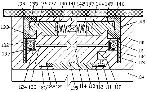
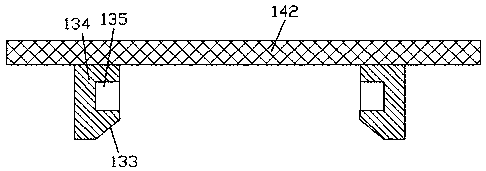
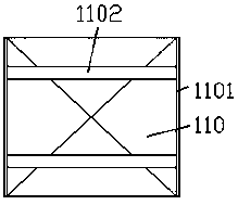
[0011] Combine below Figure 1-3 The present invention will be described in detail.

[0012] refer to Figure 1-3 , a photovoltaic building module device according to an embodiment of the present invention, including a mounting platform 100 mounted on a base 104 in a rotational fit and a photovoltaic device plugged and connected to the mounting platform 100 , the top end surface of the mounting platform 100 An insertion groove 148 is symmetrically arranged on the left and right, and the inner wall of the insertion groove 148 is connected with a perforation 145, and the inner wall of the perforation 145 is connected with a sliding groove 140, and a sliding block 144 is slidably fitted in the sliding groove 140, The outer end surface of the sliding block 144 is fixed with a locking arm 136, and the locking arm 136 is slidably connected to the through hole 145. The upper side of the outer end surface of the locking arm 136 is provided with a pushing slope 146, and the locking ar...


PUM


Abstract

The invention discloses a photovoltaic building module device. The device comprises a mounting table rotatably and cooperatively arranged on a base and photovoltaic equipment cooperatively inserted inthe mounting table, insertion grooves are left and right symmetrically formed in the top end face of the mounting table, and through holes are communicated with the inner side walls of the insertiongrooves; sliding grooves are communicated with the inner side walls of the through holes, sliding blocks are slidingly and cooperatively arranged in the sliding grooves, and locking arms are fixedly arranged on the outer side end faces of the sliding blocks and slidingly and cooperatively connected with the through holes; top push inclined surfaces are arranged at the upper sides of the outer sideend faces of the locking arms; magnetic blocks are arranged in the sliding grooves in the inner side end faces of the locking arms, top press springs are cooperatively arranged on the portions, in the sliding grooves in the inner side end faces of the locking arms, at the outer sides of the magnetic blocks through top press, and an electromagnetic coil device opposite to the magnetic blocks is fixedly arranged on the portion, in the inner wall of the mounting table, between the sliding grooves in the left and right sides.

Description

technical field [0001] The invention relates to the field of new energy technologies, in particular to a photovoltaic building module device. Background technique [0002] Using the abundant solar energy in desert areas to generate electricity has become a new way to use deserts. When building a power station, the installation of solar photovoltaic panels is an important step. The current installation steps of solar photovoltaic panels are cumbersome and are usually fixed on the installation bracket. The angle cannot be adjusted according to the rotation and work of the earth, therefore, the efficiency of solar energy absorption and conversion is reduced. Therefore, it is necessary to design a photovoltaic building module device that is easy to install and adjustable in angle. Contents of the invention [0003] The object of the present invention is to provide a photovoltaic building module device for overcoming the above-mentioned defects in the prior art. [0004] Accor...

Claims


Application Information

Patent Timeline
Patent Type & Authority Applications(China)
IPC IPC(8): H02S20/30H02S30/00F24S30/425
CPCH02S30/00H02S20/30Y02B10/10Y02B10/20Y02E10/50
Inventor 林海燕王雪双汪碧芳
Owner 黄种继
Why Eureka
Try Eureka