Constant-temperature control method, heating device and storage medium

A constant temperature control and heating device technology, applied in the direction of electric heating devices, electrical components, etc., can solve the problems of poor applicability, dependence on temperature sensors, and inability to meet the needs of constant temperature control, and achieve the effect of improving applicability and high temperature control accuracy

Active Publication Date: 2018-08-03
张宜悦
View PDF18 Cites 10 Cited by
  • Summary
  • Abstract
  • Description
  • Claims
  • Application Information

AI Technical Summary

Problems solved by technology

[0003] One is to control the power-on time of the heater to achieve temperature control; the circuit adopted in this method is simple, but the temperature control accuracy is poor, which cannot meet the constant temperature control requirements
[0004] The other is to add a temperature sensor on the heater, or add a temperature sensor to the terminal equipment, and use the feedback data of the temperature sensor to control the switching time of the heater to achieve the purpose of constant temperature; but this method must rely on the temperature sensor. has certain limitations and poor applicability

Method used


Image

  • Constant-temperature control method, heating device and storage medium
  • Constant-temperature control method, heating device and storage medium
  • Constant-temperature control method, heating device and storage medium

Examples


Embodiment Construction

[0056] It should be understood that the specific embodiments described here are only used to explain the present invention, not to limit the present invention.

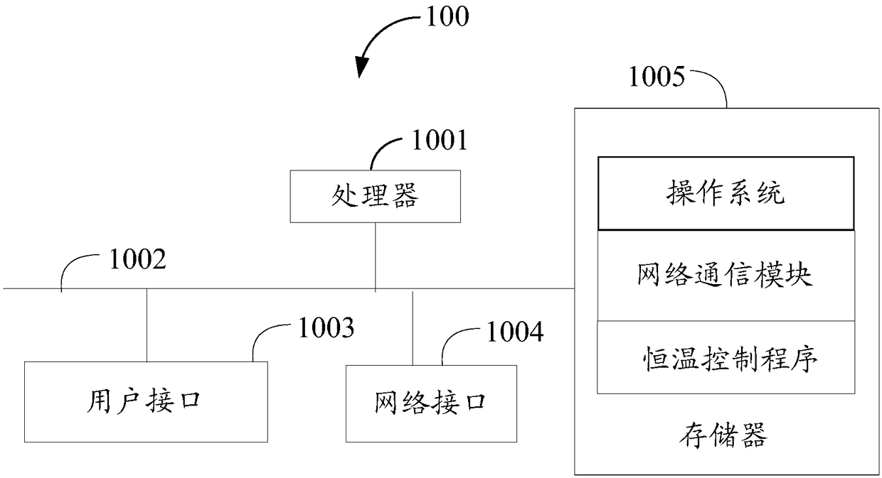
[0057] Such as figure 1 as shown, figure 1 It is a schematic diagram of the hardware structure of an embodiment of the heating device of the present invention.

[0058] The heating device 100 of the present application can be an aroma diffuser, an electric faucet, an electric blanket, an electric iron, an electric soldering iron, a heat gun, a heat fan, an electric heater, a floor heater, an electric rice cooker, an electric saucepan, an electric frying pan, an electric furnace, an electric water heater , Moxibustion device, electric gloves, electric clothes, electric insoles, electric belts, electric vests, tin stoves, reflow soldering or incubators, etc.

[0059] Such as figure 1 As shown, the heating device 100 may include: a processor 1001 , such as an MCU, a network interface 1004 , a user interface 1003 , a m...


PUM


Abstract

The invention discloses a constant-temperature control method. A heating component is controlled to heat or stop heating by calculating a resistance value RA of the heating component under a target temperature Tt, detecting a resistance value RB of the heating component under a heating state and according to a comparison result between the RB and the RA, and the temperature of the heating component is maintained at a target temperature Tt. The invention also discloses a heating device and a storage medium. By the constant-temperature control method, the accuracy and the applicability of constant-temperature control are improved.

Description

technical field [0001] The invention relates to the technical field of temperature control, in particular to a constant temperature control method, a heating device and a storage medium. Background technique [0002] In the existing temperature control field, there are mainly two ways to achieve the temperature control effect. [0003] One is to control the power-on time of the heater to achieve temperature control; this method uses a simple circuit, but the temperature control accuracy is poor, and it cannot meet the needs of constant temperature control. [0004] The other is to add a temperature sensor on the heater, or add a temperature sensor to the terminal equipment, and use the feedback data of the temperature sensor to control the switching time of the heater to achieve the purpose of constant temperature; but this method must rely on the temperature sensor. It has certain limitations and poor applicability. Contents of the invention [0005] The main purpose of...

Claims


Application Information

Patent Timeline
Patent Type & Authority Applications(China)
IPC IPC(8): H05B1/00
CPCH05B1/02H05B1/0252
Inventor 张宜悦
Owner 张宜悦
Why Eureka
Try Eureka