Conveying belt device

A conveyor belt and transmission mechanism technology, applied in the direction of lifting devices, hoisting devices, conveyor objects, etc., can solve the problems of not being able to meet the requirements of automatic pick-up by manipulators, failure of trolley limit warning, shortening the service life of trolleys, etc., to achieve stable transmission Good performance, faster production tempo, and novel structure

Pending Publication Date: 2018-08-07
沈阳英联精密模塑有限公司
View PDF11 Cites 0 Cited by
  • Summary
  • Abstract
  • Description
  • Claims
  • Application Information

AI Technical Summary

Problems solved by technology

[0002] When the threshold is produced on the 1850T equipment, due to the limitations of the equipment, it cannot satisfy the automatic pick-up of the manipulator, and the transmission devices are all driven by electric power, which consumes a lot of power, high energy consumption for production, and insufficient transportation stability; the conveyor belt device in the prior art It is impossible to carry out limit warning for the trolley, which will easily cause the trolley to collide with the bracket and shorten the service life of the trolley. Therefore, a simple conveyor belt device is urgently needed to solve the above problems

Method used


Image

  • Conveying belt device
  • Conveying belt device

Examples


Embodiment approach

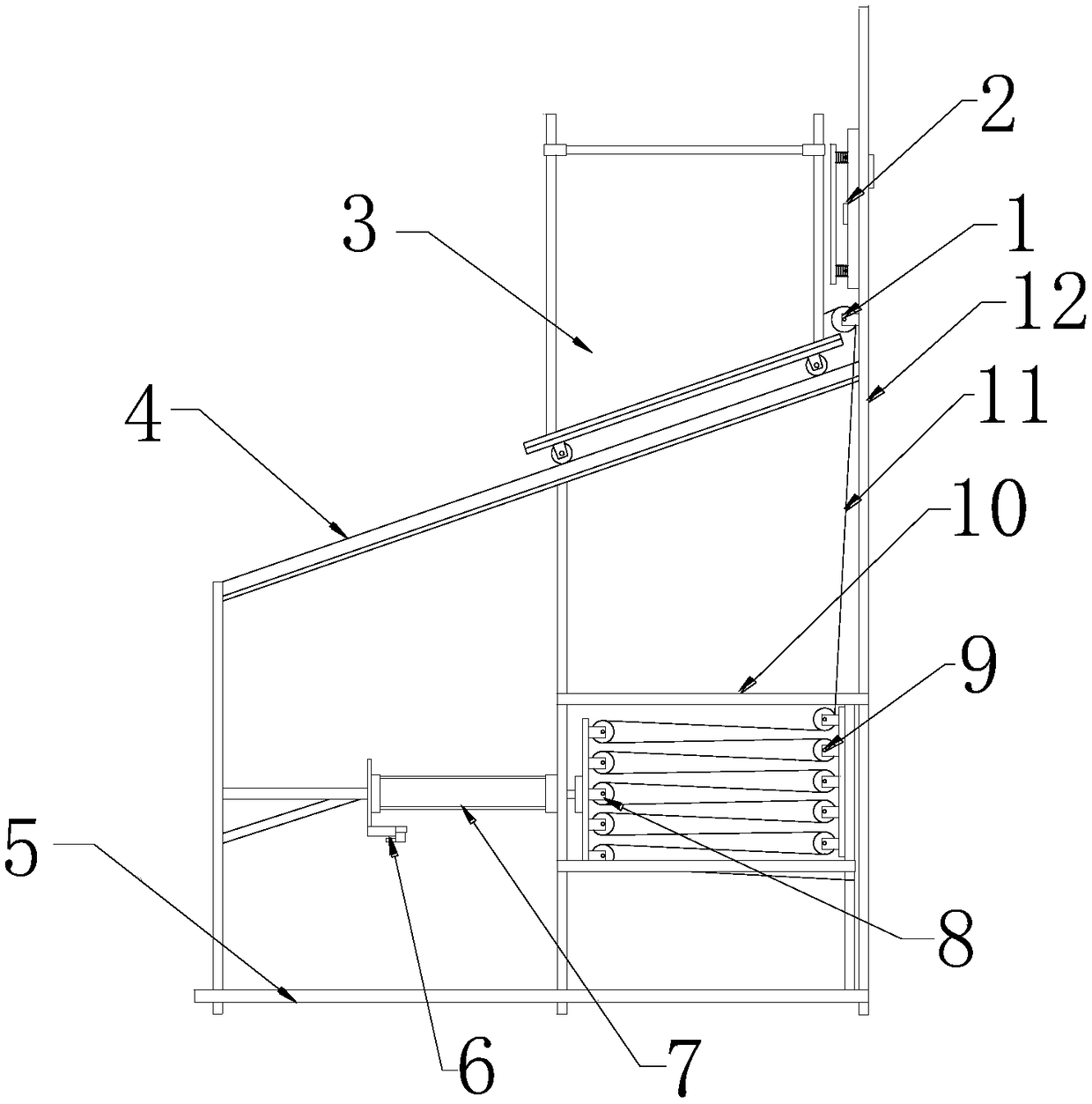
[0022] Specific implementation method: when in use, the mold is opened, and the working signal is output to the manipulator. The solenoid valve 6 obtains the signal of mold opening, and outputs it to the cylinder 7, and then the cylinder 7 contracts. The contraction of the cylinder 7 drives the moving pulley carrier to move to the left, and the moving pulley The movement of the carrier plate drives the movable pulley block 8 to move, and the movable pulley block 8 moves to stretch the steel wire rope 11, and then the steel wire rope 11 drives the fixed pulley block 9 and the upper fixed pulley 1 to rotate. 3. Move the top position of the carrier 4 to receive the product grabbed by the manipulator. When the product is placed on the trolley 3, the cylinder 7 is running, and the cylinder 7 is ejected, and then the movable pulley carrier plate drives the movable pulley block 8 to move to the right, thereby relaxing the wire rope 11 , under the gravity of the trolley 3 itself, the s...


PUM


Abstract

The invention provides a conveying belt device. The conveying belt device comprises an upper fixed pulley, an air cylinder, a movable pulley group, a fixed pulley group, a wire rope, a travel switch,a limiting plate and a spring; the upper fixed pulley is fixed on the upper portion of the left end face of a supporting frame, the air cylinder is installed on the left side of the supporting frame,the movable pulley group is installed on the right end face of a fixed pulley loading plate, the fixed pulley group is installed on the inner right end face of a pulley loading frame, the upper end ofthe wire rope is connected with the right end of a trolley, and the lower end of the wire rope sequentially penetrates through the upper fixed pulley, the fixed pulley group and the movable pulley group and is connected with the right end of the pulley loading frame. By means of the device, the takt time is accelerated to ensure the quality of products, the travel switch is installed in the middle of the left end face of an upright plate, the limiting plate is fixed at the left end of the limiting plate, and the spring is fixed on the left end face of the upright plate; a function of limitingearly warning of the trolley is achieved. The device has the advantages of being novel in structure, excellent in conveying stability, free from electric drive, and low in production cost.

Description

technical field [0001] The invention relates to a conveyor belt device, which belongs to the technical field of tooling in the injection molding industry. Background technique [0002] When the threshold is produced on the 1850T equipment, due to the limitations of the equipment, it cannot satisfy the automatic pick-up of the manipulator, and the transmission devices are all driven by electric power, which consumes a lot of power, high energy consumption for production, and insufficient transportation stability; the conveyor belt device in the prior art It is impossible to carry out limit warning for the trolley, which will easily cause the trolley to collide with the bracket and shorten the service life of the trolley. Therefore, a simple conveyor belt device is urgently needed to solve the above-mentioned problems. Contents of the invention [0003] Aiming at the deficiencies in the prior art, the object of the present invention is to provide a conveyor belt device to so...

Claims


Application Information

Patent Timeline
Patent Type & Authority Applications(China)
IPC IPC(8): B65G47/90B66F19/00
CPCB65G47/90B66F19/00
Inventor 何震栾硕昆张蒙赵辉
Owner 沈阳英联精密模塑有限公司
Why Eureka
Try Eureka