
Liquid carbon dioxide dry-process sand fracturing system and technological process

A liquid carbon dioxide and sand fracturing technology, which is applied in the direction of sustainable manufacturing/processing, mining fluid, wellbore/well components, etc., can solve the problems of insufficient construction displacement, large waste of liquid carbon dioxide, and high noise, and achieve improvement Improve construction safety, achieve concentrated emission, and reduce construction noise

Pending Publication Date: 2018-08-07
BC P INC CHINA NAT PETROLEUM CORP +1
View PDF14 Cites 13 Cited by
  • Summary
  • Abstract
  • Description
  • Claims
  • Application Information

AI Technical Summary

Problems solved by technology

[0004] In order to overcome the defects existing in the prior art, the present invention provides a liquid carbon dioxide dry sanding fracturing system and process flow, which solves the problems of insufficient construction displacement, large waste of liquid carbon dioxide, and high noise

Method used

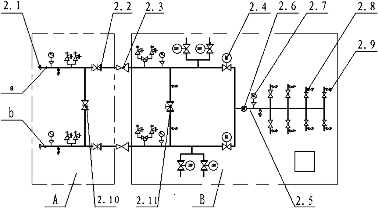

Image

  • Liquid carbon dioxide dry-process sand fracturing system and technological process
  • Liquid carbon dioxide dry-process sand fracturing system and technological process
  • Liquid carbon dioxide dry-process sand fracturing system and technological process

Examples


Embodiment 1

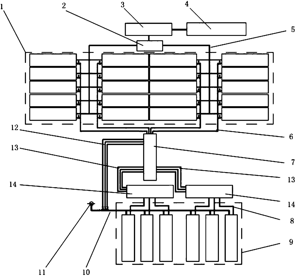
[0035] like figure 1 As shown, the liquid carbon dioxide dry sand fracturing system includes at least a liquid nitrogen tanker 4, a liquid nitrogen pump 3, a nitrogen booster 2, a carbon dioxide storage tank 1, a circulating cooling device 7, a closed sand mixing device 14 and a press The split car 9, the liquid nitrogen tank car 4, the liquid nitrogen pump car 3, and the nitrogen booster 2 are sequentially connected through pipelines, the nitrogen booster 2 is connected to the carbon dioxide storage tank 1 through the gas phase pipeline 5 of the carbon dioxide storage tank, and the carbon dioxide storage tank 1. The liquid phase pipeline 6 of the carbon dioxide storage tank is connected to the circulating cooling device 7. The circulating cooling device 7 is connected to the closed sand mixing device 14 through the liquid inlet pipeline 13 of the closed sand mixing device. The closed sand mixing device 14 is connected to the water supply pipeline 8 of the fracturing vehicle. ...

Embodiment 2

[0046] On the basis of Embodiment 1, the fracturing vehicle 9 is provided with a high-pressure pipeline 10, and the high-pressure pipeline 10 is connected to the circulating cooling device 7 through the circulating cooling device return line 12, so that the circulating cooling device 7, the closed sand mixing device 14 A circulation loop is formed with the fracturing vehicle 9 .

[0047] The nitrogen pressurization device 2, the carbon dioxide storage tank 1, the circulating cooling device 7 and the closed sand mixing device 14 are respectively connected to a remote control cabinet for remote data collection, centralized control and recording.

Embodiment 3

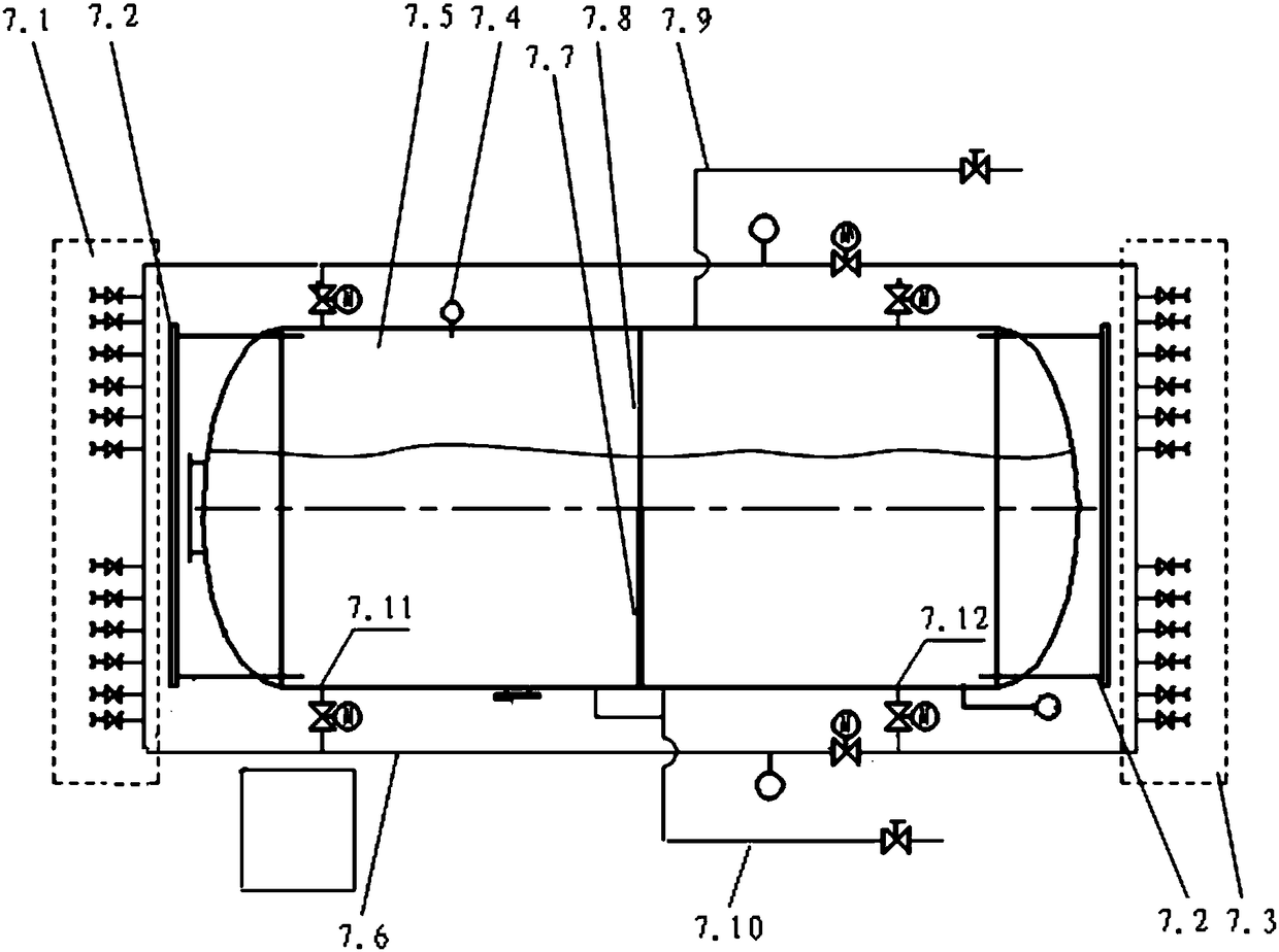
[0049] On the basis of the above examples, if image 3 As shown, the circulating cooling device 7 belongs to a horizontal layout, including a tank body 7.5, which is a professional liquid carbon dioxide storage tank, and the left and right ends of the tank body 7.5 are equipped with a liquid level gauge 7.2, and the left side of the tank body 7.5 is sealed. A manhole is provided, a pressure sensor 7.4, a safety valve, and a gas phase pipeline 7.9 are provided on the top of the tank body 7.5, a partition 7.7 is provided at the bottom of the tank body 7.5, and a walkway that can be opened and closed is provided on the partition 7.7. A filter screen 7.8; a temperature sensor is provided at the bottom of the tank body 7.5, and residual liquid discharge ports are provided on both sides of the bottom partition plate 7.7 of the tank body 7.5, and the two residual liquid discharge ports are combined into a residual liquid discharge pipeline 7.10;

[0050] A liquid inlet 7.11 is arrang...


PUM


Abstract

The invention discloses a liquid carbon dioxide dry-process sand fracturing system and a technological process. The liquid carbon dioxide dry-process sand fracturing system at least comprises a carbondioxide storage tank, a nitrogen pressurization device, a liquid nitrogen pump truck, a liquid nitrogen tank truck, a circulating cooling device, a fracturing truck and a sealed sand mixing device. The liquid nitrogen tank truck, the liquid nitrogen pump truck and the nitrogen pressurization device are sequentially connected through a pipeline. The nitrogen pressurization device is connected withthe carbon dioxide storage tank through a carbon dioxide storage tank gas-phase pipeline. The carbon dioxide storage tank is connected with the circulating cooling device through a carbon dioxide storage tank liquid-phase pipeline. The circulating cooling device is connected with the sealed sand mixing device through a sealed sand mixing device liquid inlet pipeline. The sealed sand mixing deviceis connected with the fracturing truck through a fracturing truck water feeding pipeline. The ground technological process can realize large discharge capacity construction, the concentrated emissionof gaseous carbon dioxide and the zero emission of gaseous carbon dioxide are realized in the pump cooling process of the fracturing truck, repeated use of carbon dioxide can be realized, and the construction cost is reduced.

Description

technical field [0001] The invention belongs to the technical field of oil and gas field development, and in particular relates to a liquid carbon dioxide dry sand fracturing system and a process flow. Background technique [0002] Carbon dioxide fracturing is an emerging fracturing technology. The main methods include carbon dioxide energized fracturing, carbon dioxide dry sand fracturing, etc. Carbon dioxide energized fracturing is usually combined with hydraulic fracturing. First, liquid carbon dioxide is used as the front After the fluid is pumped into the target layer by the fracturing vehicle, the well is shut down, and then hydraulic sand fracturing is performed. During the flowback process of the fracturing fluid after construction, the carbon dioxide in the target layer is used to quickly flow back the fracturing fluid, which can reduce the water base pressure. The damage of cracking fluid to sensitive formations. Carbon dioxide dry sand fracturing has good applica...

Claims


Application Information

Patent Timeline
Patent Type & Authority Applications(China)
IPC IPC(8): E21B43/26E21B43/16
CPCE21B43/164E21B43/26Y02P90/70
Inventor 杨延增章东哲宋振云叶文勇聂俊郑维师刘广春韩旭辉贾建鹏魏小房谭欢姜和
Owner BC P INC CHINA NAT PETROLEUM CORP
Learn More