Space millimeter wave wireless energy transmission system

A wireless energy transmission, millimeter wave technology, applied in circuit devices, electrical components, etc., can solve the problems of large volume and weight of transmitting/receiving antennas, insufficient practicability, transmission distance and antenna aperture bottlenecks, etc., to maximize transmission efficiency , the effect of reducing the volume and weight, and solving the bottleneck between the transmission distance and the antenna aperture

Active Publication Date: 2018-08-07
SHANGHAI INST OF SPACE POWER SOURCES
View PDF0 Cites 1 Cited by
  • Summary
  • Abstract
  • Description
  • Claims
  • Application Information

AI Technical Summary

Problems solved by technology

[0003] The purpose of the present invention is to provide a space millimeter wave wireless energy transmission system, which uses the Ka millimeter wave band for wireless energy transmission, realizes energy transmission with high distance-to-diameter ratio, solves the bottleneck between the transmission distance and the antenna aperture, and overcomes the traditional microwave The energy transmission system needs to be equipped with a transmitting / receiving antenna, and the volume and weight of the transmitting / receiving antenna are too large, resulting in insufficient practicability

Method used


Image

  • Space millimeter wave wireless energy transmission system
  • Space millimeter wave wireless energy transmission system
  • Space millimeter wave wireless energy transmission system

Examples


Embodiment Construction

[0043] The present invention will be further elaborated below by describing a preferred specific embodiment in detail in conjunction with the accompanying drawings.

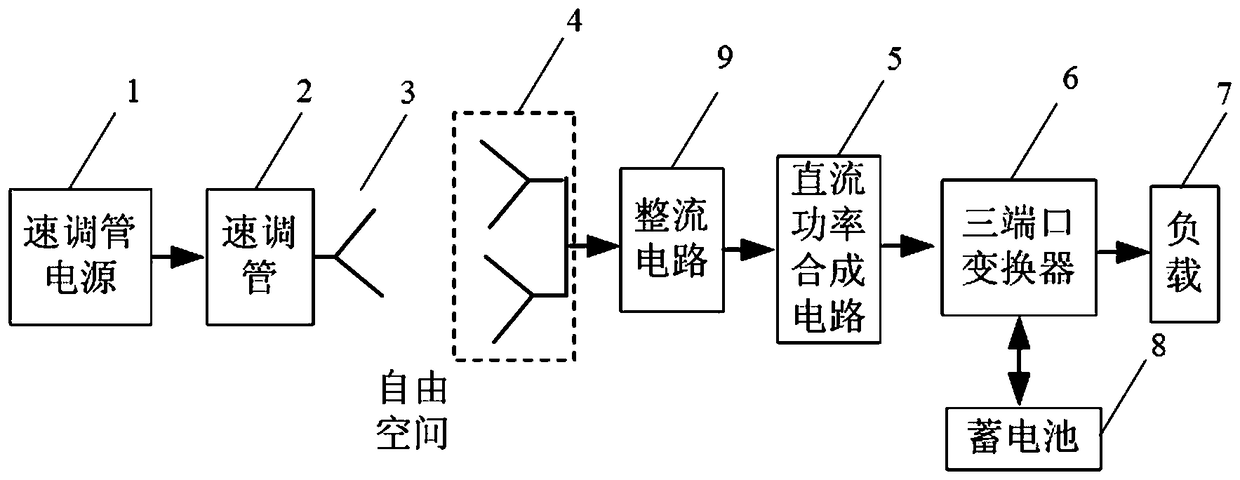
[0044] Such as figure 1 As shown, the present invention proposes a space millimeter wave wireless energy transmission system, which performs wireless energy transmission in the Ka band, preferably in the 35GHz millimeter wave band. The space millimeter wave wireless energy transmission system includes: klystron Power supply 1, with constant current input and multiple high-voltage outputs, is used to test the function of the continuous emission millimeter-wave klystron and generate microwave power; the continuous emission millimeter-wave klystron 2 is connected to the klystron power supply 1 for To generate millimeter wave energy, in this embodiment, the continuous emitting millimeter wave klystron 2 adopts an all-metal ceramic structure, and is connected by argon arc welding by electron gun, high frequency intera...


PUM


Abstract

The invention discloses a space millimeter wave wireless energy transmission system. The space millimeter wave wireless energy transmission system comprises a klystron power source; a continuous transmitting millimeter wave klystron connected with the klystron power source, a millimeter wave transmitting antenna of which an input end is connected with the millimeter wave klystron, a receiving antenna array which is arranged in the free space, is arranged corresponding to the millimeter wave transmitting antenna and comprises at least one receiving antenna, a rectifying circuit of which an input end is connected with an output end of the receiving antenna array, a DC power synthesizing circuit of which an input end is connected with an output end of the rectifying circuit, a three-port converter of which an input end is connected with an output end of the DC power synthesizing circuit, a load of which an input end is connected with an output end of the three-port converter, and a battery connected with the three-port converter. The system is advantaged in that wireless energy transmission is carried out through utilizing a millimeter wave band, high aspect ratio energy transfer is realized, and a problem of lacking of practicality caused by the excessive volume and weight of a conventional microwave energy transmission system needing equipped with transmitting / receiving antennasis overcome.

Description

technical field [0001] The invention relates to the technical field of microwave wireless energy transmission systems in energy sources, in particular to a space millimeter wave wireless energy transmission system. Background technique [0002] As early as the 1960s, people put forward the concept of solar space power station based on microwave energy transmission technology. In the field of solar space power stations, a lot of research has been done abroad. Compared with traditional energy transmission methods, microwave energy transmission technology has its unique advantages, such as no transmission medium, fast speed, low loss, and easy re-layout, etc. However, due to the low frequency of the microwave energy transmission system in the traditional band, the transmitting / receiving antenna array is huge and weighs several tons, which is not very practical. Contents of the invention [0003] The purpose of the present invention is to provide a space millimeter wave wirel...

Claims


Application Information

Patent Timeline
Patent Type & Authority Applications(China)
IPC IPC(8): H02J50/20H02J50/27H02J50/40
CPCH02J50/20H02J50/27H02J50/40
Inventor 何小斌蓝剑宇谢伟黄军
Owner SHANGHAI INST OF SPACE POWER SOURCES
Why Eureka
Try Eureka