
Oil transmission line pipe inner wall derusting and drying automation equipment

A technology of automatic equipment and lines, applied in drying, dryer, metal processing equipment and other directions, can solve the problems of large power waste, high processing efficiency of the inner wall of the pipeline, and complicated operation.

Inactive Publication Date: 2018-08-10
张浩
View PDF0 Cites 2 Cited by
  • Summary
  • Abstract
  • Description
  • Claims
  • Application Information

AI Technical Summary

Problems solved by technology

[0004] In order to solve the above problems, the present invention provides an automatic equipment for derusting and drying the inner wall of oil pipeline pipelines, which can solve the problems of complex operation, slow processing speed of Long rust removal time, poor rust removal and polishing effect, inability to dry in a local area, large power waste, poor drying effect and low work efficiency, etc., can realize continuous and stable rust removal and drying functions on the inner wall of oil pipelines, without the need for intermediate Replacement equipment operation, fast processing speed of the inner wall of the pipeline, high processing efficiency of the inner wall of the pipeline, high work efficiency, short derusting and polishing time, good derusting and polishing effect, fast drying in a local area, good power saving performance and drying effect Good and other advantages, providing a new way of integrated treatment of the inner wall of oil pipelines

Method used


Image

  • Oil transmission line pipe inner wall derusting and drying automation equipment
  • Oil transmission line pipe inner wall derusting and drying automation equipment
  • Oil transmission line pipe inner wall derusting and drying automation equipment

Examples


Embodiment Construction

[0022] In order to make the technical means, creative features, goals and effects achieved by the present invention easy to understand, the present invention will be further described below in conjunction with specific illustrations.

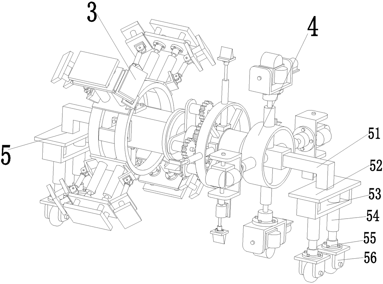
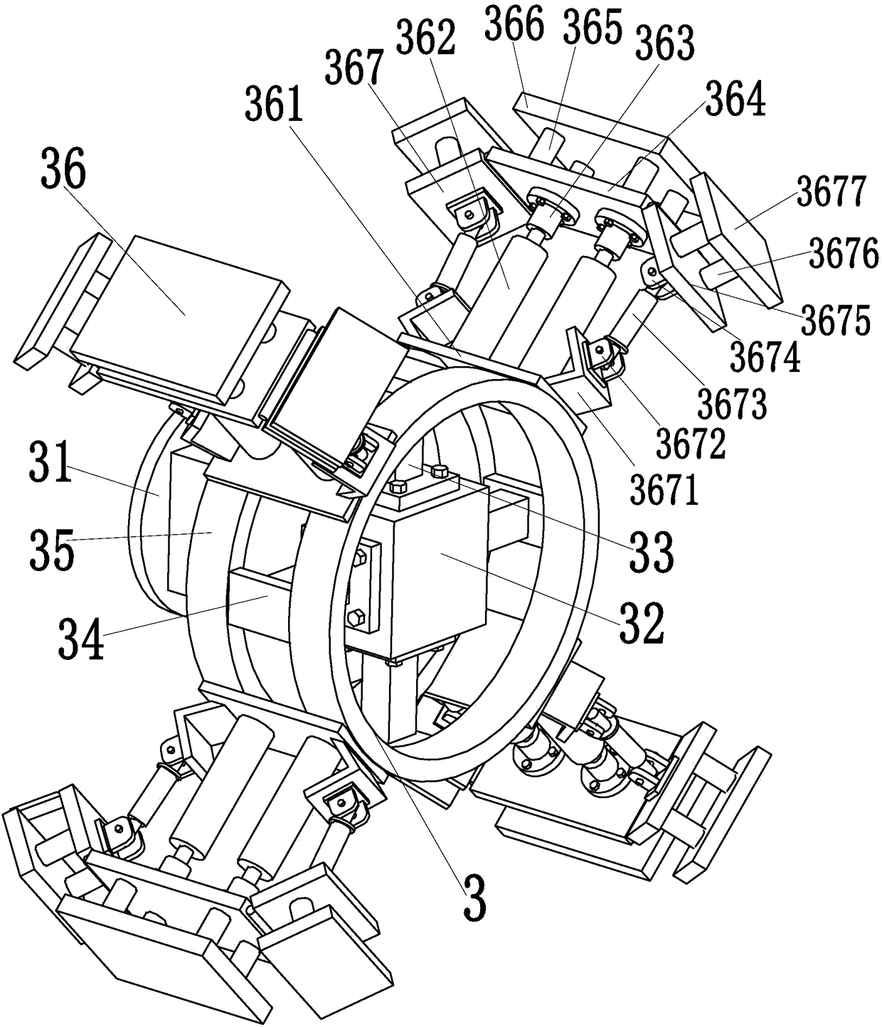
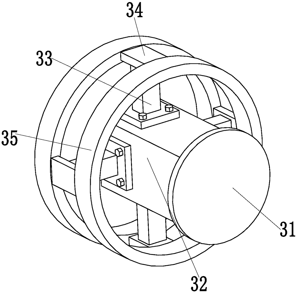
[0023] Such as Figure 1 to Figure 8 As shown, an automatic equipment for derusting and drying the inner wall of the oil pipeline pipeline includes an inner wall drying device 3, which can realize the rapid drying function of the inner wall of the pipeline, and can perform local rapid drying according to the actual situation of the inner wall of the pipeline , wide application range, good power saving performance, and good drying effect. The inner wall derusting device 4 is installed on the right side of the inner wall drying device 3, and the inner wall derusting device 4 can realize rapid scraping and derusting of impurities on the inner wall of the pipeline. Grinding function, short derusting and grinding time, good derusting and grinding effec...


PUM


Abstract

The invention relates to oil transmission line pipe inner wall derusting and drying automation equipment. The equipment comprises an inner wall drying device; the inner wall drying device can realizequick drying function for pipe inner walls, and can locally and quickly dry the pipe inner walls according to actual conditions to achieve wide application range; an inner wall derusting device is mounted on the right side of the inner wall drying device; the inner wall derusting device can realize quick impurity scraping and derusting polishing functions for the pipe inner walls; and walking branch chains are welded at the left end of the inner wall drying device and the right end of the inner wall derusting device. The two walking branch chains walk on the pipe inner walls, and comprise L-shaped walking support columns; the two L-shaped walking support columns on the two walking branch chains are respectively welded on the inner wall drying device and the inner wall derusting device; andwalking baseplates are welded at the tail ends of the L-shaped walking support columns. The equipment can realize continuous and stable derusting and drying functions for the inner walls of petroleumpipes, and is high in pipe inner wall treatment speed and pipe inner wall treatment efficiency.

Description

[0001] The present invention is a divisional application of a Chinese patent application filed on July 16, 2016 with the application number 2016105603926 and the title of the invention is an integrated machine for intelligent drying and rust removal on the inner wall of oil pipelines. technical field [0002] The invention relates to the technical field of petroleum pipeline machinery, in particular to an automatic equipment for derusting and drying the inner wall of an oil pipeline pipeline. Background technique [0003] With the rapid development of the petroleum industry, more and more oil pipelines and water injection pipelines are used in oil fields. Oil and water usually contain corrosive substances, which often lead to pipeline corrosion damage, especially the life of oil pipelines with high water content and sewage reinjection pipelines is greatly shortened, and the replacement of new pipelines faces huge costs. Corroded old pipelines need anti-corrosion treatment. T...

Claims


Application Information

Patent Timeline
Patent Type & Authority Applications(China)
IPC IPC(8): B24B27/033B24B41/00B24B41/02B24B41/04F26B23/06
CPCB24B27/033B24B41/00B24B41/002B24B41/02B24B41/04B24B47/12F26B23/06
Inventor 张浩
Owner 张浩
Learn More