Numerical control spinning frame head transmission device

A transmission device and locomotive technology, applied to spinning machines, continuous winding spinning machines, textiles and papermaking, etc., can solve the problems of high labor intensity, gear damage, complex system mechanism, etc., and achieve simple and effective structure. The effect of prolonging the service life and improving production efficiency

Pending Publication Date: 2018-08-10
江苏格罗瑞节能科技有限公司
View PDF11 Cites 0 Cited by
  • Summary
  • Abstract
  • Description
  • Claims
  • Application Information

AI Technical Summary

Problems solved by technology

[0003] The transmission of the headstock of the CNC spinning machine in the prior art is generally realized through a gearbox. In the mechanical transmission wheel train, the more gears, the greater the probability of damage to the gears. The system mechanism is complicated, and it is necessary to change the variety and adjust the rollers When the distance is longer, the labor intensity of the workers is also greater
The traditional gearbox transmission mode can no longer meet the needs of modern textile production

Method used


Image

  • Numerical control spinning frame head transmission device
  • Numerical control spinning frame head transmission device
  • Numerical control spinning frame head transmission device

Examples


Embodiment Construction

[0018] The present invention will be described in further detail below in conjunction with examples and specific implementation methods.

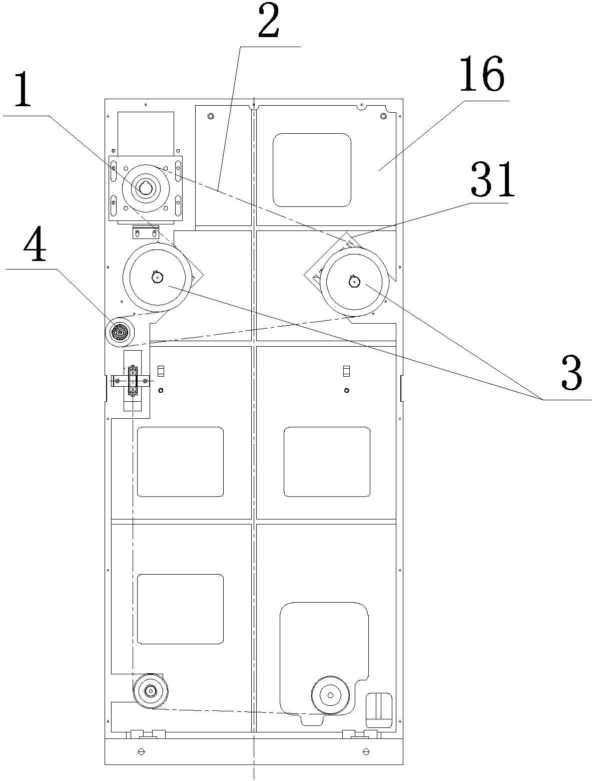
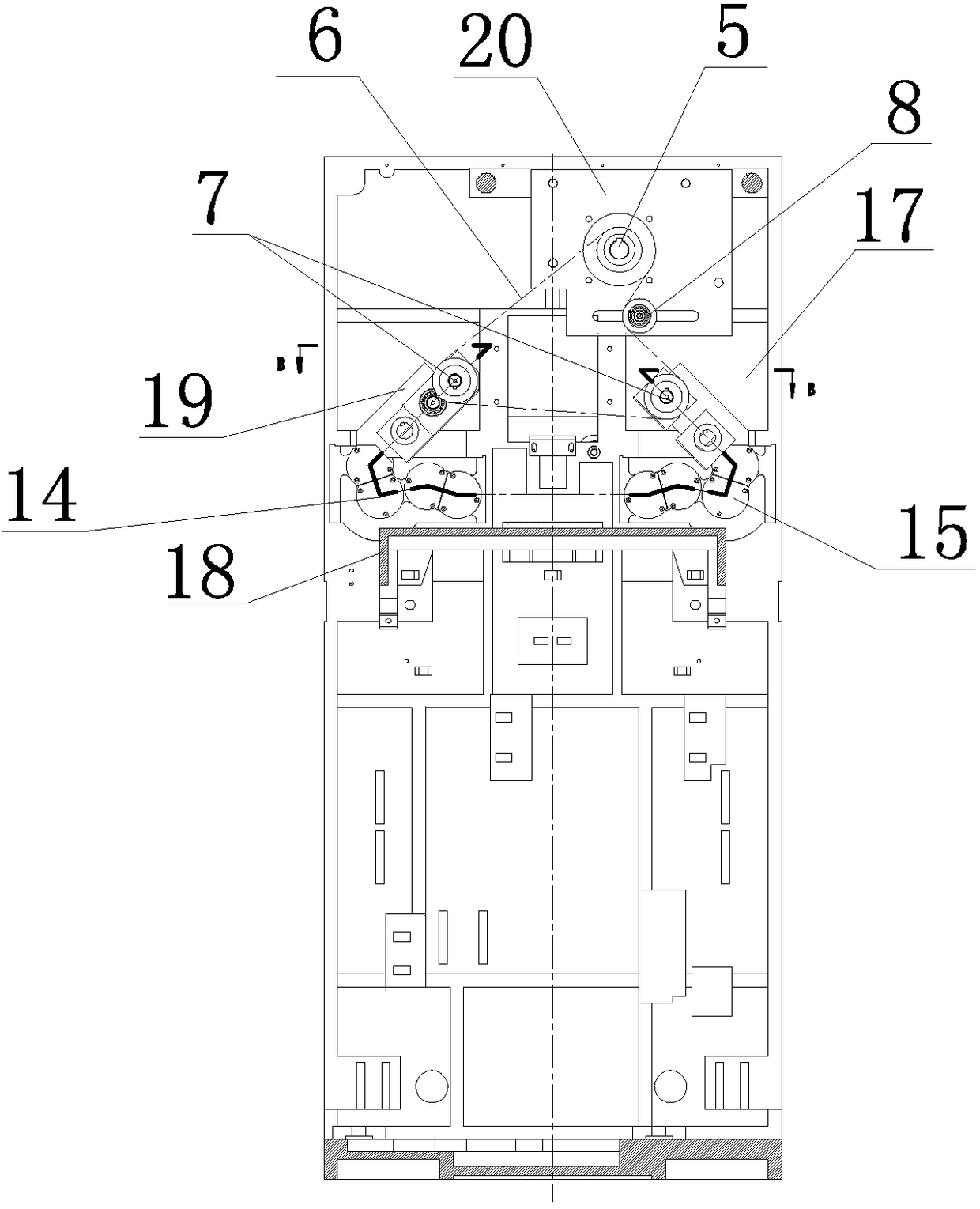
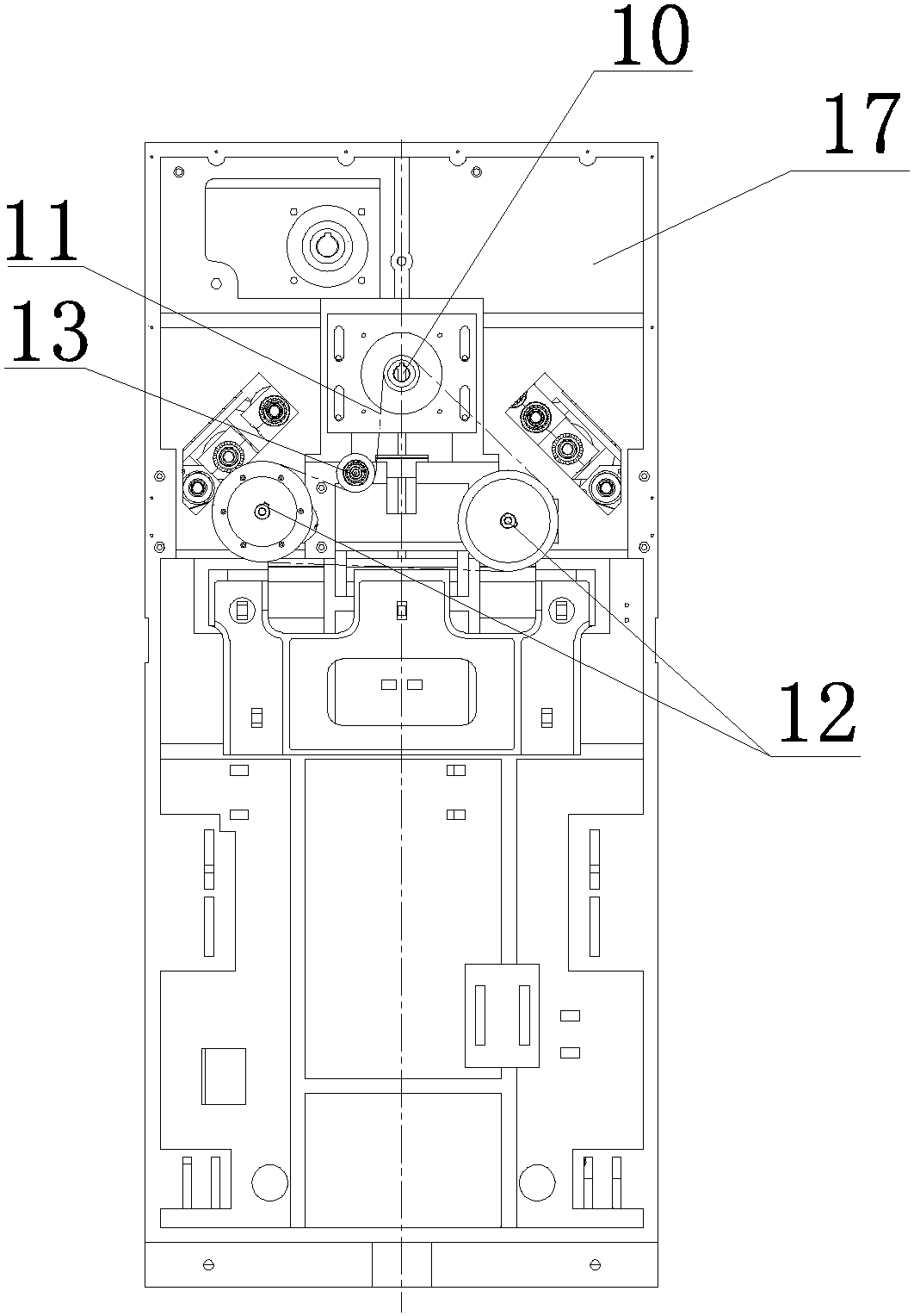
[0019] As shown in the accompanying drawings, the transmission device of the headstock of the CNC spinning machine has a structure including the front roller A, the middle roller B, the rear roller C, the outer vertical mounting plate 16 and the inner vertical mounting plate 17 on both sides, wherein the inner vertical mounting plate 17 and the inner vertical mounting plate 17 The outer vertical mounting plate 16 is arranged in parallel, the middle part between the outer vertical mounting plate 16 and the inner vertical mounting plate 17 is provided with a horizontal mounting plate 18, and the outer vertical mounting plate 16 is provided with a middle roller motor, a reduction box 1 and two middle roller synchronous pulleys 3. The synchronous belt pulley at the end of the output shaft of the middle roller motor and the reduction box 1 is con...


PUM


Abstract

The invention provides a numerical control spinning frame head transmission device. According to the structure of the numerical control spinning frame head transmission device, a horizontal mounting plate is arranged in the middle of the portion between an outer vertical mounting plate and an inner vertical mounting plate, the outer vertical mounding plate is provided with a middle roller motor, areduction gearbox and two middle roller synchronous pulleys, the middle roller motor and a synchronous pulley at the end of an output shaft of the reduction gearbox are in transmission connection with the two middle roller synchronous pulleys through a double cogged synchronous belt, and a reverse wheel is arranged beside one of the middle roller synchronous pulleys. The double cogged synchronousbelt between the two middle roller synchronous pulleys is in transmission connection with the reverse wheel, the two middle roller synchronous pulleys are in transmission connection with the two faces of the double cogged synchronous belt respectively, the rotation directions of the two middle roller synchronous pulleys are opposite, and the two middle roller synchronous pulleys are in driving connection with two middle rollers respectively. The numerical control spinning frame head transmission device has the advantages that the distance between rollers can be easily adjusted, the rotation directions of the rollers on both sides can be easily transformed, the device can be suitable for production of various textile products, the production efficiency is improved, and the service life isprolonged.

Description

technical field [0001] The invention relates to a transmission device of a numerically controlled spinning machine headstock. Background technique [0002] Spinning frame is actually a spinning machine that drafts, twists, and winds semi-finished roving or sliver into spun bobbin during the spinning process. Spinning frame is the main machine for spinning. [0003] The transmission of the headstock of the CNC spinning machine in the prior art is generally realized by a gearbox. In the mechanical transmission wheel train, the more gears there are, the greater the probability of damage to the gears. When the distance is longer, the labor intensity of the workers is also greater. The traditional gearbox transmission mode can no longer meet the needs of modern textile production. Contents of the invention [0004] The present invention proposes a transmission device for the headstock of a CNC spinning frame, and its purpose is to overcome the above-mentioned deficiencies in ...

Claims


Application Information

Patent Timeline
Patent Type & Authority Applications(China)
IPC IPC(8): D01H1/34D01H1/22D01H5/44
CPCD01H1/22D01H1/34D01H5/44
Inventor 葛陈鹏
Owner 江苏格罗瑞节能科技有限公司
Why Eureka
Try Eureka