Combined vibration damping device

A vibration damping device and component technology, which is applied in the direction of shock absorbers, inertia effect shock absorbers, shock absorbers, etc., can solve the problem of reducing the width of the vibration isolation frequency domain, difficult to quasi-zero dynamic stiffness, and bending of the resonance peak section, etc. The problem is to reduce the degree of nonlinear stiffness, compact structure, and widen the vibration isolation frequency band.

Active Publication Date: 2018-08-10
WUHAN POLYTECHNIC UNIVERSITY
View PDF5 Cites 17 Cited by
  • Summary
  • Abstract
  • Description
  • Claims
  • Application Information

AI Technical Summary

Problems solved by technology

Without affecting the static bearing capacity of the vibration isolation system and the quality of the vibration-isolated parts, people have proposed a variety of positive and negative stiffness elastic parts connected in parallel, so that the vibration of the vibration isolation system near the static equilibrium position has quasi-zero dynamic stiffness (low dynamic stiffness-high static stiffness), but due to the existence of influencing factors such as load mismatch, material performance deviation, manufacturing, and assembly errors of the vibration isolation system, near the static equilibrium position of the load, the load of the vibration isolation system The negative stiffness of the stiffness elastic element cannot completely offset the positive stiffness of the positive stiffness elastic element, and it is difficult to truly achieve quasi-zero dynamic stiffness; in addition, the use of negative stiffness elastic elements will introduce nonlinear stiffness. Generally speaking, for quasi-zero dynamic stiffness Stiffness vibration isolation system, strong nonlinear stiffness is beneficial to improve the vibration isolation performance, but the existence of strong nonlinear stiffness makes the resonance peak section of the frequency response curve of the vibration isolation system seriously bent, resulting in a decrease in the width of the vibration isolation frequency domain, There will also be response jumps, causing deterioration of vibration isolation performance

Method used


Image

  • Combined vibration damping device
  • Combined vibration damping device
  • Combined vibration damping device

Examples


Embodiment Construction

[0030] The following will clearly and completely describe the technical solutions in the embodiments of the present invention with reference to the accompanying drawings in the embodiments of the present invention. Obviously, the described embodiments are only part of the embodiments of the present invention, not all of them. Based on the embodiments of the present invention, all other embodiments obtained by persons of ordinary skill in the art without creative efforts fall within the protection scope of the present invention.

[0031] It should be noted that if there is a directional indication (such as up, down, left, right, front, back...) in the embodiment of the present invention, the directional indication is only used to explain the position in a certain posture (as shown in the accompanying drawing). If the specific posture changes, the directional indication will also change accordingly.

[0032] In addition, if there are descriptions involving "first", "second" and ...


PUM


Abstract

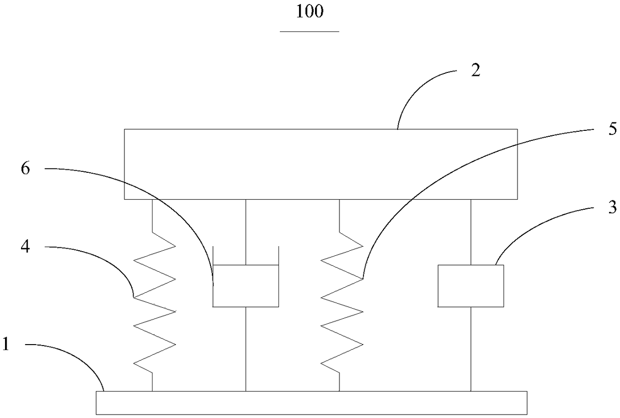
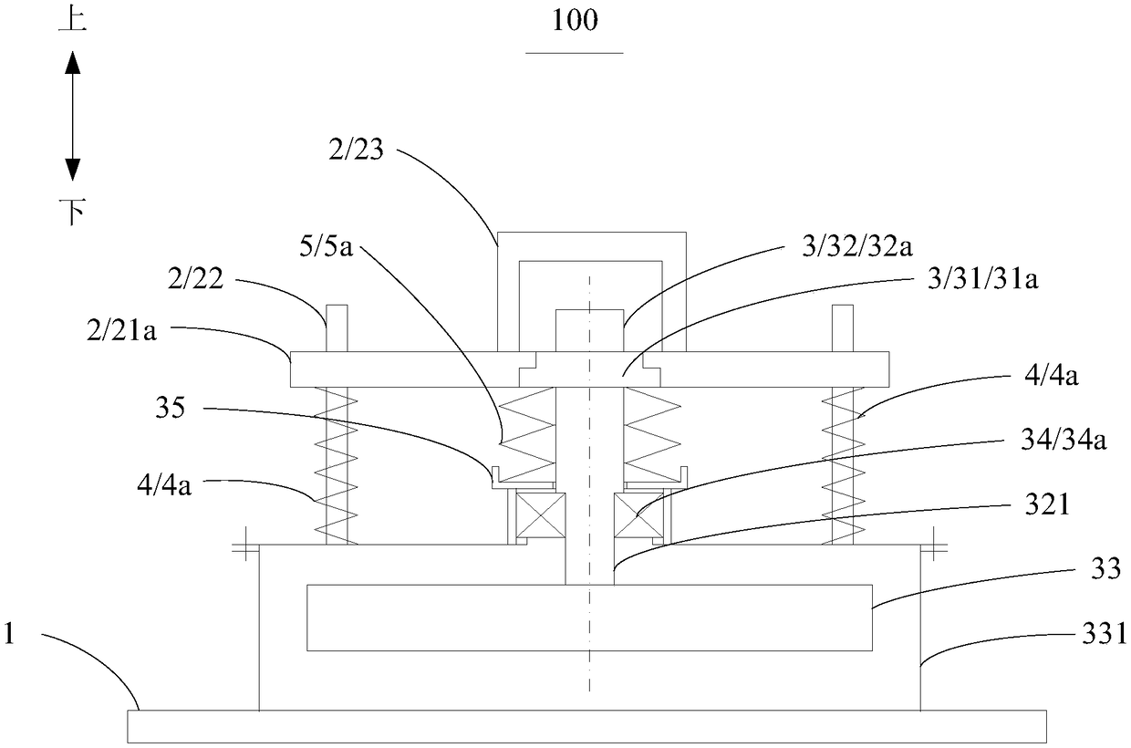
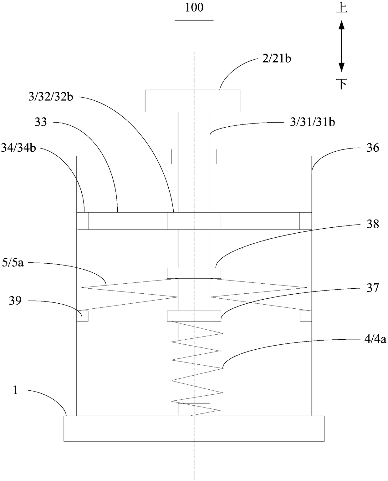
The invention discloses a combined vibration damping device. The combined vibration damping device comprises a pedestal, a bearing structure, an inerter, a positive stiffness component and a negativestiffness component; the bearing structure is arranged above the pedestal; the inerter comprises a linear actuating part, a rotating part, a transmission mechanism and a flywheel, wherein the transmission mechanism is in transmission connection with the linear actuating part and the rotating part; the linear actuating part extends in the vertical direction; the upper end of the linear actuating part is directly or indirectly connected with the bearing structure; the rotating part is arranged at the lower end of the linear actuating part; the transmission mechanism is used for transforming up-and-down movement of the linear actuating part into horizontal rotation of the rotating part; the flywheel is installed at the rotating part; the upper end of the positive stiffness component is directly or indirectly connected with the bearing structure; the lower end of the positive stiffness component is directly or indirectly connected with the pedestal; the upper end of the negative stiffnesscomponent is directly or indirectly connected with the baring structure; the lower end of the negative stiffness component is directly or indirectly connected with the pedestal, wherein the positive stiffness component and the negative stiffness component are used for bearing the weight of the bearing structure; and the inerter and the negative stiffness perform combined action in order to reducethe inherent frequency of the vibration damping device and optimize the vibration damping effect of the vibration damping device.

Description

technical field [0001] The invention relates to the technical field of vibration damping devices, in particular to a combined vibration damping device. Background technique [0002] The impact of vibration on precision instruments and mechanical equipment cannot be ignored. In precision mechanical systems, vibration is a significant source of degraded system performance. The main adverse effect on precision machining and precision measurement is the slight low-frequency vibration within 0.5-70Hz; the energy of vibration during vehicle driving is mainly distributed in the frequency range of 0-200Hz, especially the energy in the frequency range of 0.5-25Hz is the most concentrated. The traditional passive vibration isolation has a simple structure, is easy to implement, works stably and reliably, and does not consume extra energy from the outside world. It has always been highly valued by the scientific and industrial circles. But once its structure is determined, its natur...

Claims


Application Information

Patent Timeline
Patent Type & Authority Applications(China)
IPC IPC(8): F16F7/10F16F7/104
CPCF16F7/1028F16F7/104
Inventor 张家凡叶建平
Owner WUHAN POLYTECHNIC UNIVERSITY
Why Eureka
Try Eureka