Deicing device of liquid natural gas output pipeline

A liquid natural gas and output pipeline technology, applied in the geometry/arrangement/dimension of container structure, pipe components, fixed-capacity gas storage tanks, etc., can solve problems such as damage to gas output pipelines, and achieve convenient installation and disassembly processes. Contact area, effect of reducing bond strength

Inactive Publication Date: 2018-08-10
北京东方通捷燃气有限责任公司
View PDF5 Cites 4 Cited by
  • Summary
  • Abstract
  • Description
  • Claims
  • Application Information

AI Technical Summary

Problems solved by technology

However, the frost condensation coating is fixed on the outer surface of the gas output pipeline relatively tightly, and it takes a lot of manpower to break it. Excessive impact force will also cause greater damage to the gas output pipeline.

Method used


Image

  • Deicing device of liquid natural gas output pipeline
  • Deicing device of liquid natural gas output pipeline
  • Deicing device of liquid natural gas output pipeline

Examples


Embodiment

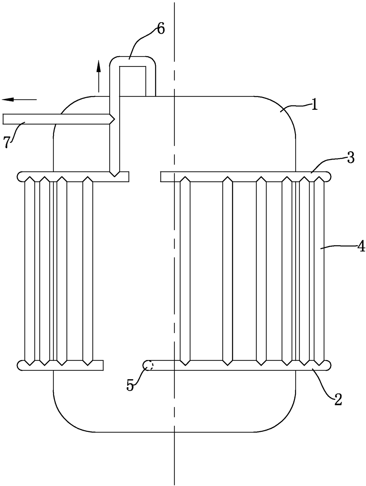
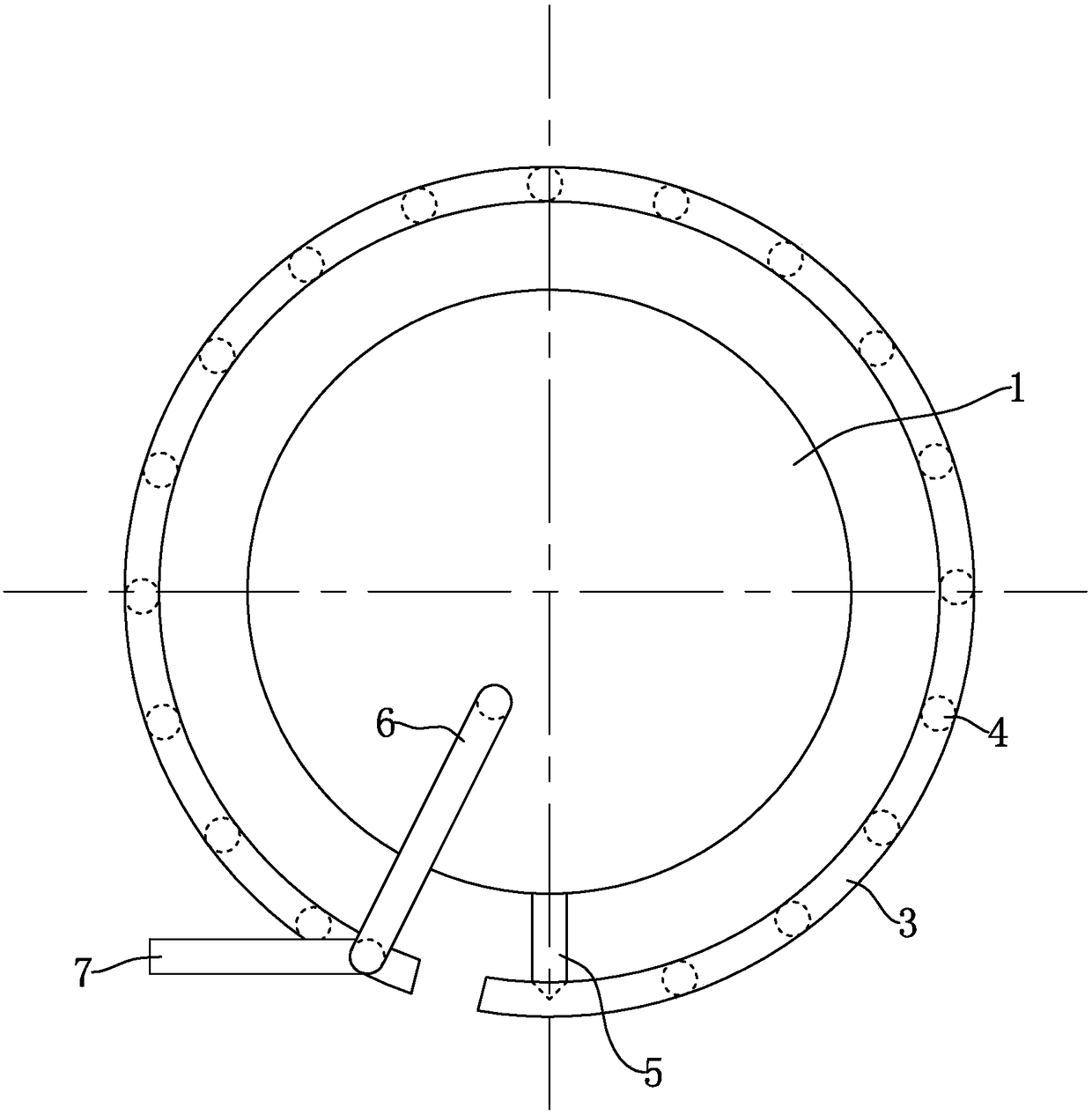
[0057] In order to facilitate the understanding of the present invention, the structure and working principle of the prior art will be briefly described first. Such as figure 1 with figure 2 As shown, the liquid natural gas storage tank 1 is surrounded by a gas outlet pipe assembly. The gas outlet pipe assembly includes a horizontally arranged gas outlet pipe 2 and an upper outlet pipe 3. Both the gas outlet pipe 2 and the upper outlet pipe 3 have disconnected gaps. The ring shape is arranged around the liquid natural gas storage tank 1; a transition pipe 4 is provided between the gas output pipe 2 and the upper output pipe 3, and the gas output pipe 2 and the upper output pipe 3 are connected through the transition pipe 4, and the transition pipe 4 are vertically arranged, and there are multiple transition pipes 4 that are evenly distributed around the circumference of the liquid natural gas storage tank 1. One end of the gas output pipe 2 is fixedly connected with a lower...


PUM


Abstract

The invention discloses a deicing device of a liquid natural gas output pipeline. The deicing device is characterized in that whole vertical sectional plates are distributed along the length directionof the gas output pipeline; the distance between every two adjacent whole vertical sectional plates ranges from 5-25 cm, the whole vertical sectional plates are perpendicular to the fuel gas output pipeline, and the whole vertical sectional plates are detachably propped against the fuel gas output pipeline in a sleeving mode; and after the whole vertical sectional plates are detached from the fuel gas output pipeline, frost left on the fuel gas output pipeline can be divided into a plurality of sections, the contact area between each section of frost and the gas output pipeline is reduced, the bonding strength between the frost and the fuel gas output pipeline is reduced, the frost can be easily knocked out or pried out from the fuel gas output pipeline, knocking strength for deicing is small, and the damage to the fuel gas output pipeline is relatively small.

Description

technical field [0001] The invention relates to an output pipeline of a liquefied natural gas storage tank, in particular to a deicing device for a liquefied natural gas output pipeline. Background technique [0002] The liquid natural gas storage tank is referred to as the LNG storage tank for short. It is a double-layer structure. There is a vacuum between the inner tank and the outer layer. [0003] In the existing technology, such as figure 1 with figure 2 As shown, the liquid natural gas storage tank 1 is surrounded by a gas outlet pipe assembly. The gas outlet pipe assembly includes a horizontally arranged gas outlet pipe 2 and an upper outlet pipe 3. Both the gas outlet pipe 2 and the upper outlet pipe 3 have disconnected gaps. It is circular and arranged around the liquid natural gas storage tank 1; the gas output pipe 2 and the upper output pipe 3 are connected through a transition pipe 4, and the transition pipe 4 is vertically arranged, and the transition pipe ...

Claims


Application Information

Patent Timeline
Patent Type & Authority Applications(China)
IPC IPC(8): F17C13/00F16L55/00F17C7/04
CPCF16L55/00F17C7/04F17C13/00F17C2201/032F17C2221/033F17C2223/0161F17C2225/0123F17C2227/0192F17C2227/0309F17C2227/039
Inventor 赵子川燕运生孔祥洲
Owner 北京东方通捷燃气有限责任公司
Why Eureka
Try Eureka