Special wiring rod for large current generator
A technology of high current generator and connecting rod, which is applied in the parts, instruments, measuring electricity and other directions of electrical measuring instruments, can solve the problems of high structure, large volume, and high physical consumption of test personnel, and achieves convenient disassembly and assembly, avoiding the need for The effect of security risks
- Summary
- Abstract
- Description
- Claims
- Application Information
AI Technical Summary
Problems solved by technology
Method used
Image
Examples
Embodiment Construction
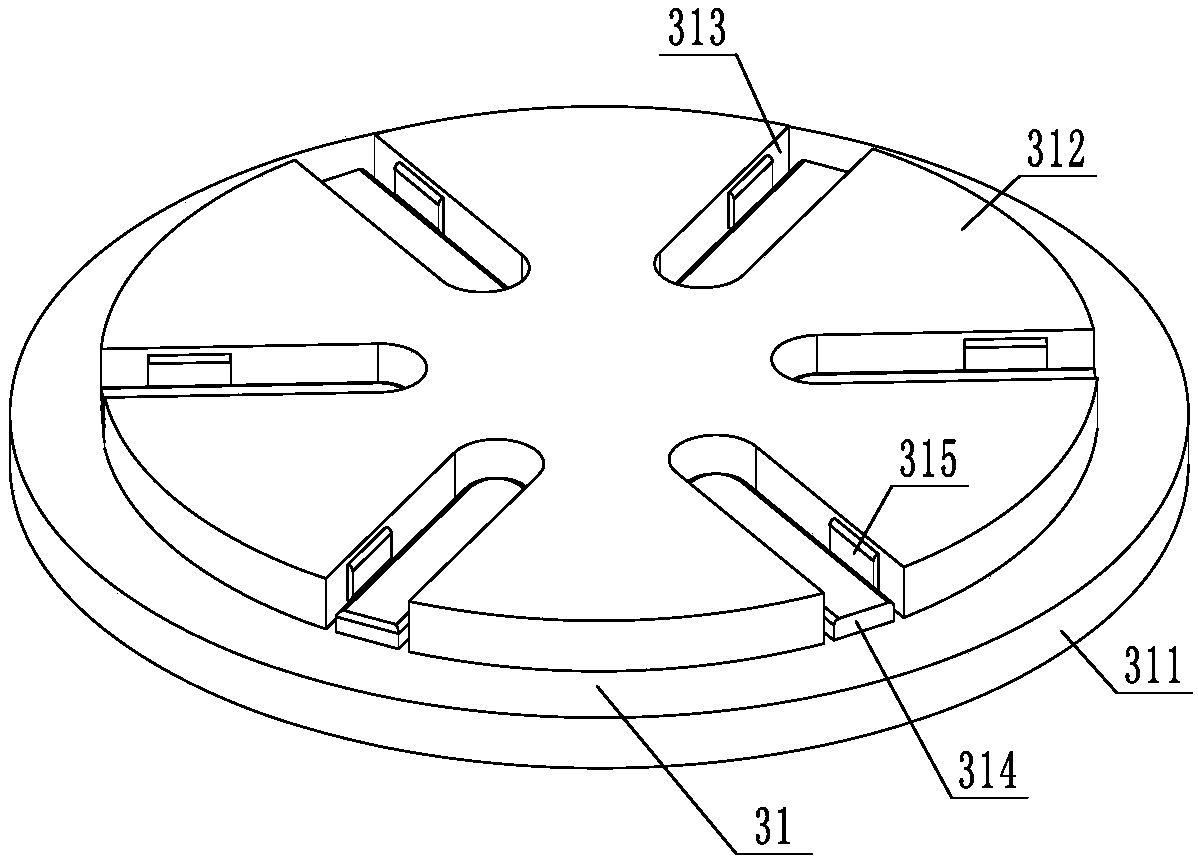
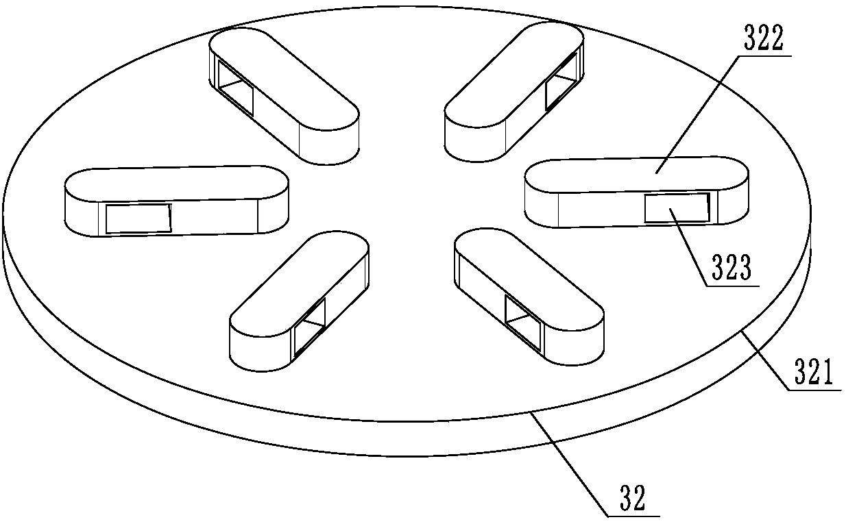
[0028] like figure 1 As shown, a special wiring rod for a large current generator includes a double-tongue hook 11, and two screws 12 are arranged on the double-tongue hook, and the screws are used to connect a 5-meter-long test lead. The lower side of the double-tongue hook A universal joint 13 is connected, and the universal joint is connected with an insulating rod 14. The insulating rod can be provided with multiple sections, and a tightening mechanism 3 is provided between adjacent insulating rods or between the universal joint and the insulating rod. An insulating rubber handle 15 is provided at the lower end of the insulating rod.
[0029] In order to optimize the design of the scheme, the insulating rod can adopt a telescopic rod design. For example, the first insulating rod can be slidably fitted in the second insulating rod and positioned at one place on the second insulating rod, and the second insulating rod can be positioned on the third insulating rod. The insul...
PUM
 Abstract
Description
Claims
Application Information
 - R&D
- Intellectual Property
- Life Sciences
- Materials
- Tech Scout
- Unparalleled Data Quality
- Higher Quality Content
- 60% Fewer Hallucinations
Browse by: Latest US Patents, China's latest patents, Technical Efficacy Thesaurus, Application Domain, Technology Topic, Popular Technical Reports.
© 2025 PatSnap. All rights reserved.Legal|Privacy policy|Modern Slavery Act Transparency Statement|Sitemap|About US| Contact US: help@patsnap.com


