Separately excited ultrasonic driving power supply
What is Al technical title?
Al technical title is built by PatSnap Al team. It summarizes the technical point description of the patent document.
A technology for driving power supply and ultrasonic wave, which is applied in the direction of electrical components, output power conversion device, AC power input conversion to AC power output, etc. Inverter PWM duty cycle loss and other problems, to achieve the effect of reducing PWM duty cycle loss, reducing switching loss, and improving output efficiency
Inactive Publication Date: 2018-08-10
邵立新
View PDF0 Cites 0 Cited by
Summary
Abstract
Description
Claims
Application Information
AI Technical Summary
This helps you quickly interpret patents by identifying the three key elements:
Problems solved by technology
Method used
Benefits of technology
Problems solved by technology
Most of the externally excited ultrasonic driving power supplies in the current technology use half-bridge high-frequency inverters. However, the PWM duty ratio of the half-bridge high-frequency inverters is seriously lost, and the switching loss of the MOS tubes is too large, resulting in its power output. Low efficiency, this problem is particularly prominent in high-power ultrasonic generators
Method used
Image
Click on the blue label to locate the original text in one second.
Reading with bidirectional positioning of images and text.
Examples
Embodiment
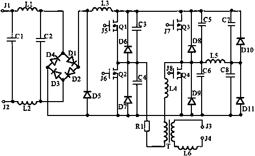
[0014] Example: such as figure 1 As shown, the separately excited ultrasonic driving power supply of this embodiment includes a rectifier bridge stack, an inductor L1, an inductor L2, an inductor L3, an inductor L4, an inductor L5, an inductor L6, a diode D5, a diode D6, a diode D7, a diode D8, and a diode D9. , diode D10, diode D11, P-channel MOS tube Q1, P-channel MOS tube Q2, P-channel MOS tube Q3, P-channel MOS tube Q4, high-frequency transformer T, capacitor C1, capacitor C2, capacitor C3, capacitor C4, capacitor C5, capacitor C6, capacitor C7, capacitor C8, resistor R1, terminal J1, terminal J2, terminal J3, terminal J4, terminal J5, terminal J6, terminal J7 and terminal J8; rectification The bridge stack includes diode D1, diode D2, diode D3, and diode D4; J1 is connected to one end of C1 and one end of L1 at the same time, J2 is connected to the other end of C1 and one end of L2 at the same time, J3 is connected to one end of the secondary winding of T, and J4 is conne...
PUM
Abstract
The invention provides a separately excited ultrasonic driving power supply, which comprises an inductor L1, an inductor L2, an inductor L3, an inductor L4, an inductor L5, an inductor L6, a diode D1,a diode D2, a diode D3, a diode D4, a diode D5, a diode D6, a diode D7, a diode D8, a diode D9, a diode D9, a diode D10, a diode D11, an MOS tube Q1, an MOS tube Q2, an MOS tube Q3, an MOS tube Q4, ahigh-frequency transformer T, a capacitor C1, a capacitor C2, a capacitor C3, a capacitor C4, a capacitor C5, a capacitor C6, a capacitor C7, a capacitor C8, a resistor R1, a wiring terminal J1, a wiring terminal J2, a wiring terminal J3, a wiring terminal J4, a wiring terminal J5, a wiring terminal J6, a wiring terminal J7 and a wiring terminal J8. J1 is connected with one end of C1 and one endof L1. J2 is connected with the other end of C1 and the other end of L2. J3 is connected with one end of the secondary winding of T. J4 is connected in series with L6 and is connected with the other end of the secondary winding of T. J5 is connected with the grid electrode of Q1. J6 is connected with the grid electrode of Q2. J7 is connected with the grid electrode of Q3. J8 is connected with thegrid electrode of Q4. One end of the primary winding of T is connected with L4 in series, and then is connected with the source electrode of Q3 and the drain electrode of Q4. The other end of the primary winding of T is connected with R1 in series and then is connected with the source electrode of Q1 and the drain electrode of Q2. The drain electrode of Q1 is connected with the drain electrode ofQ3. The source electrode of Q2 is connected with the source electrode of Q4. The invention has the following advantages: a full-bridge high-frequency inverter circuit structure with a built-in auxiliary network is used for replacing a half-bridge structure in the prior art, so that the loss of a PWM duty cycle is greatly reduced. Therefore, the switch loss of MOS tubes under the high-frequency condition can be greatly reduced, so that the output efficiency of a high-power ultrasonic generator is greatly improved.
Description
technical field [0001] The invention relates to an ultrasonic generator power supply assembly, in particular to a separately excited ultrasonic driving power supply. Background technique [0002] Ultrasound, especially high-power ultrasound, is widely used in medical fields such as ultrasonic cleaning, imaging, and atomization. The ultrasonic driving power supply is the power supply component of the ultrasonic generator, and its amount can convert the power frequency commercial power into high frequency alternating current for the ultrasonic transducer to generate ultrasonic waves. Ultrasonic driving power can be divided into self-excited and other-excited according to different excitation methods. The separately-excited ultrasonic driving power has more advantages in output power, so it is commonly used in current high-power ultrasonic generators. Most of the externally excited ultrasonic driving power supplies in the current technology use half-bridge high-frequency inver...
Claims
Application Information
Patent Timeline
Application Date:The date an application was filed.
Publication Date:The date a patent or application was officially published.
First Publication Date:The earliest publication date of a patent with the same application number.
Issue Date:Publication date of the patent grant document.
PCT Entry Date:The Entry date of PCT National Phase.
Estimated Expiry Date:The statutory expiry date of a patent right according to the Patent Law, and it is the longest term of protection that the patent right can achieve without the termination of the patent right due to other reasons(Term extension factor has been taken into account ).
Invalid Date:Actual expiry date is based on effective date or publication date of legal transaction data of invalid patent.