
Modified type full-bridge phase-shifted soft switch converter

A full-bridge phase-shifting and soft-switching technology, which is applied to conversion equipment without intermediate conversion to AC, DC power input to DC power output, instruments, etc., can solve the increase in circuit layout space requirements, large diode voltage stress, The secondary side duty cycle loss and other issues can improve the zero-voltage switching conditions in the full load range, the device works reliably and stably, and reduces the duty cycle loss.

Inactive Publication Date: 2009-06-17
HANGZHOU ZHONGHEN ELECTRIC CO LTD
View PDF3 Cites 0 Cited by
  • Summary
  • Abstract
  • Description
  • Claims
  • Application Information

AI Technical Summary

Problems solved by technology

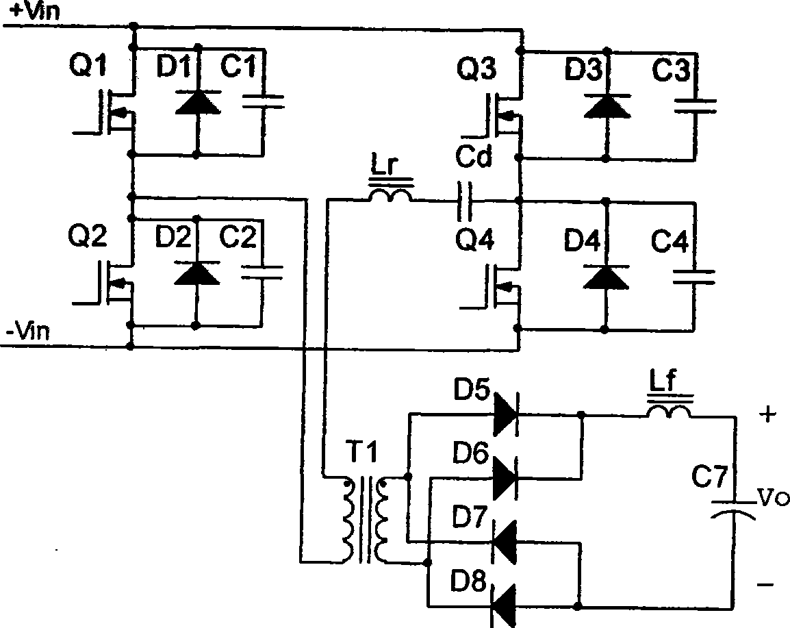
[0003] 1) As attached figure 1 As shown, when the load is light, the resonant inductor Lr has insufficient energy storage, and the zero-voltage turn-on of the hysteresis tubes Q3 and Q4 cannot be realized, the loss is large, and the energy conversion efficiency is not high;
[0004] 2) During the turn-off period of the leading tubes Q1 and Q2, the resonant inductance Lr cannot change abruptly due to the current, and there is a circulating current in the loop formed by D2, T1, Lr, Cd, Q4 or D1, T1, Lr, Cd, and Q3, and this circulating current does not Provide energy to the secondary side, but generate losses, making the conversion efficiency of the converter low;
[0005] 3) There is a strong oscillation in the reverse recovery of the secondary diodes D5~D8, and the voltage stress on the diodes is relatively large, which requires high electrical parameters of the diodes and reduces the reliability of the system. If the absorption circuit is added to improve the stress, the loss of the whole machine will increase , reducing conversion efficiency;
[0006] 4) The existence of the resonant inductance Lr will cause the loss of the duty cycle of the secondary side, which will also reduce the conversion efficiency of the converter
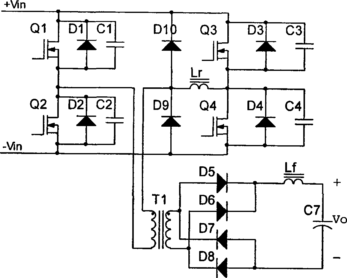
[0007] Another example figure 2 Shown is the more full-bridge phase-shift soft switching circuit currently used, which is in figure 1 Based on the improvement, two clamping tubes D10 and D9 were added to improve the reverse recovery voltage stress of the secondary diodes D5-D8 and reduce the degree of duty cycle loss, but did not solve the other problems mentioned above. Several defects, adding diodes at the same time makes the structure more complicated, and the layout space requirements of the circuit increase, which is not conducive to the miniaturization of application equipment

Method used


Image

  • Modified type full-bridge phase-shifted soft switch converter
  • Modified type full-bridge phase-shifted soft switch converter
  • Modified type full-bridge phase-shifted soft switch converter

Examples


Embodiment Construction

[0026] The present invention will be further described below in conjunction with the accompanying drawings.

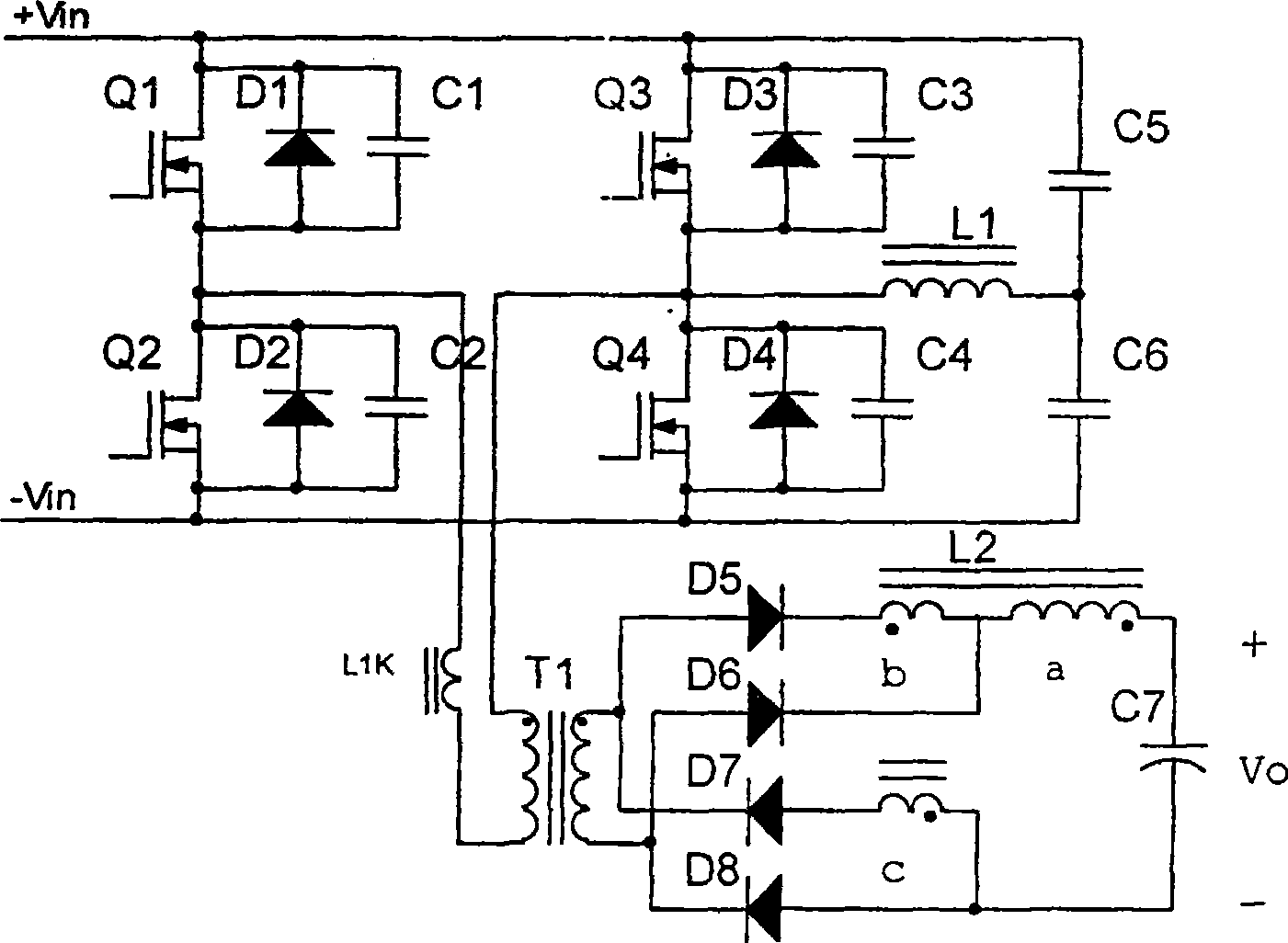
[0027] refer to Figure 3 ~ Figure 11 , an improved full-bridge phase-shifting soft-switching converter, including a leading arm branch, a lagging arm branch, a transformer T1, a filter inductor network, an output filter capacitor C7 and a load R L , the leading bridge arm branch includes transistors Q1, Q2, diodes D1, D2, capacitors C1, C2, the lagging bridge arm branch includes transistors Q3, Q4, diodes D3, D4, capacitors C3, C4, and the leading The bridge arm branch and the lagging bridge arm branch are respectively connected to the primary side of the transformer T1, where L 1k is the transformer leakage inductance, the secondary side of the transformer T1 is connected to the filter inductance network, the filter inductance network is connected to the output filter capacitor, and the load R L Connected in parallel with the output filter capacitor, the soft switc...


PUM


Abstract

The present invention relates to an improved full bridge dephasing soft switching transformer, based on the prior full bridge dephasing soft switching transformer. Tthe soft switching transformer also comprises a syntony network which comprises capacitances C5 and C6 and an inductanceL1. Wherein, one end of the capacitance C5 is connected with an input positive end, the other end of the capacitance C5 is connected with an end of the inductanceL1 and an end of the capacitance C6, the other end of the capacitance C6 is connected with an input negative end, the other end of the inductanceL1 is connected with a source electrode S of a triode Q3 and a drain electrode D of the triode Q4 of a lag bridge arm branch. The present invention provides an improved full bridge dephasing soft switching transformer which is capable of effectively lowering the circulation loss, reducing the loss of the duty ratio, increasing the effect of the complete machine and reducing the electromagnetic radiation.

Description

technical field [0001] The invention relates to a full-bridge phase-shifting soft switching device, which is suitable for various high-power switching power supply devices, especially for electric operation power supply occasions. Background technique [0002] On the basis of retaining the advantages of traditional PWM constant frequency control, the full-bridge phase-shift zero-voltage switching converter realizes soft switching by using the parasitic parameters of the device. It has been widely used in large and medium power DC / DC conversion, but the traditional The full-bridge phase-shift zero-voltage switching converter has defects, which are mainly manifested in: [0003] 1) As attached figure 1 As shown, when the load is light, the resonant inductor Lr has insufficient energy storage, and the zero-voltage turn-on of the hysteresis tubes Q3 and Q4 cannot be realized, the loss is large, and the energy conversion efficiency is not high; [0004] 2) During the turn-off p...

Claims


Application Information

Patent Timeline
Patent Type & Authority Patents(China)
IPC IPC(8): H02M3/315H02M3/07
CPCY02B70/1491Y02B70/10
Inventor 袁明祥范德育孙慧
Owner HANGZHOU ZHONGHEN ELECTRIC CO LTD
Learn More