Converter high in fuel utilization rate

A utilization rate and fuel technology, applied in the manufacture of converters, etc., can solve the problems of fuel consumption, limited air supply, serious problems, etc., and achieve the effects of improving the combustion effect, enhancing the combustion temperature, and increasing the heating speed

Inactive Publication Date: 2018-08-14
CHENGDU JUNSHUO RUIZHI INFORMATION TECH CO LTD
View PDF0 Cites 0 Cited by
  • Summary
  • Abstract
  • Description
  • Claims
  • Application Information

AI Technical Summary

Problems solved by technology

[0002] The converter is a tool used in the metal smelting process. The traditional rotary converter usually rotates around the axis of its furnace body. In its furnace, sufficient air is continuously supplied to the fuel to meet the high temperature heating requirements for various metal materials. Furnace temperature requirements, but the air used in the work of the widely used rotary converter is fed into the converter from the bottom of the converter through pipes. There are two problems in this way. Insufficient contact with the supplied air can not give full play to the heat released by fuel combustion, so that the heating speed of metal material parts is slow, resulting in longer heating time of objects, more serious fuel consumption, and increased production cost burden; 2. It is the residue produced by fuel combustion that easily blocks the air inlet pipe and prevents the outside air from entering the converter, making the fuel and air not in sufficient contact and affecting the normal operation of the converter

Method used


Image

  • Converter high in fuel utilization rate
  • Converter high in fuel utilization rate
  • Converter high in fuel utilization rate

Examples


Embodiment 1

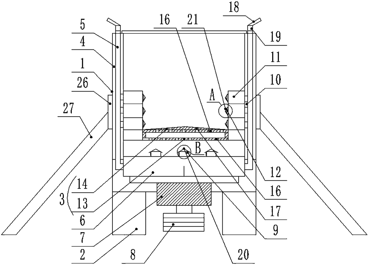
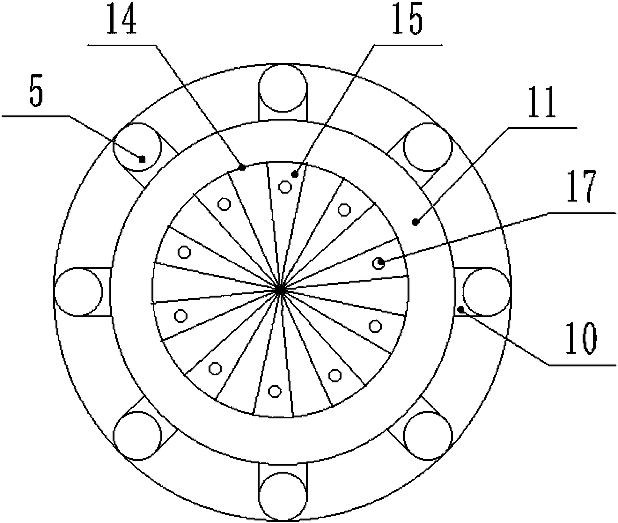
[0033] Such as Figure 1-4As shown, a converter with high fuel utilization rate includes a furnace body 1 and a furnace base 2, and the furnace body 1 is provided with a ventilation assembly and a combustion frame 3 for placing fuel; on the side wall of the furnace body 1 A cavity 4 is provided; the air guide assembly includes an air guide pipe 5, an air collection chamber 6, a ventilation assembly, a rotating shaft 7 and a motor 8, and the air guide pipe 5 runs through the cavity 4 and is circumferentially distributed on the furnace body 1, the top of the air guide pipe 5 is arranged outside the furnace body 1, and the bottom end of the air guide pipe 5 communicates with the air collection chamber 6, and the air collection chamber 6 is arranged at the bottom of the furnace body 1; the air collection chamber The top of 6 is provided with several first air outlet pipes 9;

[0034] The top of the air guide pipe 5 is provided with an air induction pipe, and the air induction pip...

Embodiment 2

[0043] Such as Figure 1-4 As shown, this implementation is further optimized on the basis of Embodiment 1. This embodiment focuses on the improvements compared with Embodiment 1, and the similarities will not be repeated. In this embodiment, the first output The outlet end of the air duct 9 is provided with a first baffle plate 20 with a herringbone cross section, the top of the first air outlet duct 9 is embedded between the first baffle plates 20, and the side of the first air outlet duct 9 The wall is provided with a through first ventilation hole 25 . The air can escape from the first ventilation hole 25 and will not be blocked by residues on the air guide pipe 5 pipes. The first baffle plate 20 can solve the problem that the residue generated by fuel combustion blocks the air guide pipe 5 pipes and prevents the outside air from entering the air guide pipe 5. In the converter, the fuel is not in sufficient contact with the air, which affects the normal operation of the c...

Embodiment 3

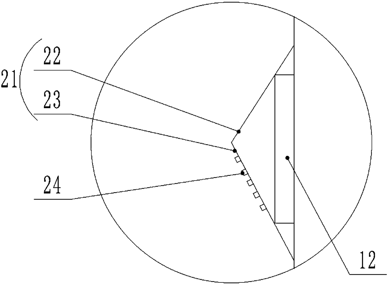
[0045] Such as Figure 1-4 As shown, this implementation is further optimized on the basis of Embodiment 1. This embodiment focuses on the improvements compared with Embodiment 1, and the similarities will not be repeated. In this embodiment, the second output The outlet end of air duct 12 is provided with the second baffle plate 21 that cross-section is herringbone, and described second baffle plate 21 is made up of upper baffle plate 22 and lower baffle plate 23, and the upper baffle plate 22 and lower baffle plate 23 One end is connected, and the other ends of the upper baffle 22 and the lower baffle 23 are respectively connected with the side wall of the ventilation chamber 11 , and the lower baffle 23 is provided with a plurality of second ventilation holes 24 . The second ventilation hole 24 on the lower baffle plate 23 can diffuse the air in the ventilation chamber 11 into the body of heater 1, so that the fuel in the burning state on the combustion rack 3 can be burned...


PUM


Abstract

The invention discloses a converter high in fuel utilization rate, belongs to the technical field of metal smelting, and aims at solving the problems that according to an existing converter, air inflow is insufficient, and ventilation holes are prone to being blocked by residues. The converter comprises a converter body and a converter base. The converter body is internally provided with a ventilation assembly and a combustion frame for containing fuel. A cavity is formed in the side wall of the converter body. An air guiding assembly comprises air guiding pipes, an air collecting chamber, a ventilation assembly, a rotation shaft and a motor, wherein the ventilation assembly comprises a ventilation pipe and a ventilation chamber. A plurality of ventilation through holes are formed in the combustion frame, and the combustion frame is located above a first air outlet pipe and arranged between inner rings of the ventilation chamber. The rotation shaft penetrates the bottom of the converter body, the top of the rotation shaft is connected with the bottom of the air collecting chamber, and the bottom of the rotation shaft is connected with the output end of the motor. The combustion frame comprises a supporting frame and a supporting disc with the section being a conical face. The supporting frame is of a hollow structure, ventilation through holes are formed in the top end and thebottom end of the supporting frame correspondingly, and the ventilation holes in the top end of the supporting frame and the ventilation holes in the bottom end of the supporting frame are arranged ina staggered manner.

Description

technical field [0001] The invention relates to the technical field of metal smelting, in particular to a converter with high fuel utilization rate. Background technique [0002] The converter is a tool used in the metal smelting process. The traditional rotary converter usually rotates around the axis of its furnace body. In its furnace, sufficient air is continuously supplied to the fuel to meet the high temperature heating requirements for various metal materials. Furnace temperature requirements, but the air used in the work of the widely used rotary converter is fed into the converter from the bottom of the converter through pipes. There are two problems in this way. Insufficient contact with the supplied air can not give full play to the heat released by fuel combustion, so that the heating speed of metal material parts is slow, resulting in longer heating time of objects, more serious fuel consumption, and increased production cost burden; 2. It is the residue produc...

Claims


Application Information

Patent Timeline
Patent Type & Authority Applications(China)
IPC IPC(8): C21C5/42
Inventor 张德彬
Owner CHENGDU JUNSHUO RUIZHI INFORMATION TECH CO LTD
Why Eureka
Try Eureka