Detachable gravity dam and construction and dismounting method thereof

A gravity dam and dismantling technology, which is applied in gravity dams, dams, etc., can solve the problems of temperature cracks, no consideration of how to disassemble the dam body, and low dam construction speed, so as to reduce temperature cracks, increase construction efficiency, and reduce engineering costs. volume and cost effects

Active Publication Date: 2018-08-14
KUNMING UNIV OF SCI & TECH
View PDF3 Cites 5 Cited by
  • Summary
  • Abstract
  • Description
  • Claims
  • Application Information

AI Technical Summary

Problems solved by technology

[0003] Aiming at the problem that the traditional high-gravity dam is prone to temperature cracks, the temperature is strictly controlled during construction, the dam-building speed is low, and the problem of how to dismantle the dam body is not considered, the present invention proposes a detachable gravity dam and its construction, Removal method

Method used


Image

  • Detachable gravity dam and construction and dismounting method thereof
  • Detachable gravity dam and construction and dismounting method thereof
  • Detachable gravity dam and construction and dismounting method thereof

Examples


Embodiment 1

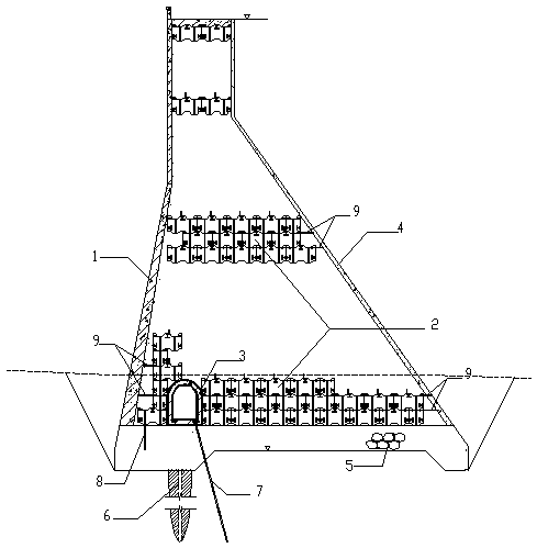
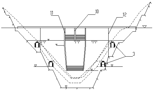
[0054] Embodiment 1: as Figure 1-11 As shown, a detachable gravity dam includes drainage grouting corridor 3, anti-seepage curtain 6, dam foundation drainage hole 7, middle pier 10, side pier 11, transverse joint 12, and upstream concrete panel 1, block concrete 2 , downstream concrete face plate 4, plain concrete cushion 5, dam foundation anchor bar 8;

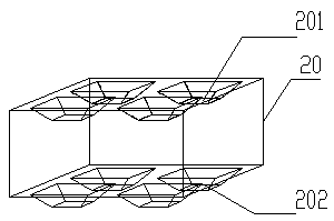
[0055] The upstream concrete panel 1 and the downstream concrete panel 4 are respectively poured on the upstream and downstream sides of the dam body, a plain concrete cushion 5 is laid on the dam foundation, and a detachable block concrete 2 is built on the plain concrete cushion 5, and the dam foundation is anchored The ribs 8 are arranged in the hoisting holes 205 of the block concrete 2 at the bottom.

[0056] Further, it can be set that the block concrete is made of prefabricated blocks connected by bolts in a certain order; specifically, it can be set that: the block concrete 2 is constructed row by row from upstream ...

Embodiment 2

[0081] Embodiment 2: as Figure 1-11 As shown, a detachable gravity dam includes drainage grouting corridor 3, anti-seepage curtain 6, dam foundation drainage hole 7, middle pier 10, side pier 11, transverse joint 12, and upstream concrete panel 1, block concrete 2 , downstream concrete face 4, plain concrete cushion 5, dam foundation anchor bar 8; described upstream concrete face 1, downstream concrete face 4 are respectively poured on the upper and lower reaches of the dam body, plain concrete cushion 5 is paved on the dam foundation, plain Detachable block concrete 2 is built on the concrete cushion 5 , and the dam foundation anchor bar 8 is arranged in the hoisting hole 205 of the bottom block concrete 2 .

[0082] Further, it can be set that the block concrete is made of prefabricated blocks connected by bolts in a certain order; specifically, it can be set that: the block concrete 2 is constructed row by row from upstream to downstream. The block concrete 2 is assembled...


PUM


Abstract

The invention relates to a detachable gravity dam and a construction and dismounting method thereof, and belongs to the technical field of water conservancy projects. The detachable gravity dam comprises a drainage grouting gallery, an anti-seepage curtain, a dam foundation drainage hole, a middle pier, a side pier and a transverse seam, and further comprises an upstream concrete panel, building block concrete, a downstream concrete panel, a plain concrete cushion layer and a dam foundation anchor bar; the building block concrete is formed by connecting prefabricated building blocks through bolts according to a certain sequence; the upstream concrete panel and the downstream concrete panel are correspondingly poured on the upper surface and the downstream side of a dam body, and the plainconcrete cushion layer is laid on the dam foundation, the detachable building block concrete is built on the plain concrete cushion layer, and the dam foundation anchor bar is arranged in each hoisting hole of the bottom-layer building block concrete. According to the detachable gravity dam and the construction and dismounting method thereof, the advantages of reliable quality and high construction efficiency of a prefabricated concrete component can be fully utilized, so that temperature cracks in the dam body are reduced, the safety of the gravity dam is ensured, meanwhile, the dam body is convenient to detach, and the economical and environment-friendly effects are realized.

Description

technical field [0001] The invention relates to a detachable gravity dam and its construction and removal methods, belonging to the technical field of hydraulic engineering. Background technique [0002] Traditional gravity dams are built by cast-in-place concrete. Since the cement in the concrete emits a large amount of heat of hydration during the hydration process, it is easy to cause large-volume concrete to form a large temperature difference with the external environment. Concrete develops cracks, thereby destroying the integrity of the concrete. In order to prevent such temperature cracks, not only artificial cooling, cooling, heat dissipation and other measures must be taken during construction, but also block and layer pouring must be adopted. The interval between two layers of pouring needs 5~10 days or longer , thus seriously affecting the construction speed. Due to the limited construction speed, the main dam body cannot realize the function of water retaining ...

Claims


Application Information

Patent Timeline
Patent Type & Authority Applications(China)
IPC IPC(8): E02B7/10
CPCE02B7/10
Inventor 魏海金格飞陈丹蕾王新陶开云宋炳月
Owner KUNMING UNIV OF SCI & TECH
Why Eureka
Try Eureka