Valve-controlled cylinder electro-hydraulic position servo system low-frequency interference compensation method

An electro-hydraulic position servo and compensation method technology, which is applied to servo motors, fluid pressure actuators, mechanical equipment, etc., can solve problems such as fluctuations, reduce the control accuracy of valve-controlled cylinder position servo systems, and affect the reproduction accuracy of given signals. , to achieve the effect of meeting real-time requirements and improving control accuracy

Active Publication Date: 2018-08-14
DALIAN MARITIME UNIVERSITY
View PDF6 Cites 10 Cited by
  • Summary
  • Abstract
  • Description
  • Claims
  • Application Information

AI Technical Summary

Problems solved by technology

Affected by the basic elasticity and the flexible connection between the hydraulic cylinder and the load, the amplitude-frequency characteristic of the closed-loop transfer function of the system position is prone to large fluctuations in the low frequency band, which greatly reduces the control accuracy of the valve-controlled cylinder position servo system
[0003] The analysis shows that when the traditional con

Method used


Image

  • Valve-controlled cylinder electro-hydraulic position servo system low-frequency interference compensation method
  • Valve-controlled cylinder electro-hydraulic position servo system low-frequency interference compensation method
  • Valve-controlled cylinder electro-hydraulic position servo system low-frequency interference compensation method

Examples


Embodiment Construction

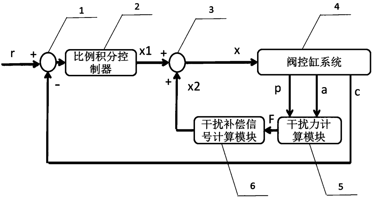
[0023] The present invention will be further described below in conjunction with the accompanying drawings. Such as figure 1 As shown, a low-frequency interference compensation method for a valve-controlled cylinder electro-hydraulic position servo system, the valve-controlled cylinder electro-hydraulic position servo system includes a subtractor 1, a proportional-integral controller 2, an adder 3, a valve-controlled cylinder system 4, Interference force calculation module 5 and interference compensation signal calculation module 6;

[0024] The low-frequency interference compensation method includes the following steps:

[0025] A. Input position command signal r;

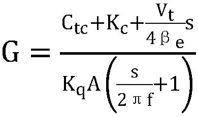
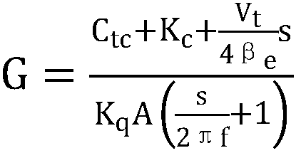
[0026] B. Using the pressure difference signal p between the two chambers of the hydraulic cylinder and the acceleration signal a of the piston rod of the hydraulic cylinder as the input signal of the interference force calculation module 5, the interference force F is obtained, and the calculation formula is: ...


PUM


Abstract

The invention discloses a valve-controlled cylinder electro-hydraulic position servo system low-frequency interference compensation method. The valve-controlled cylinder electro-hydraulic position servo system low-frequency interference compensation method comprises the steps that a position command signal r is input; a pressure difference signal p of two cavities of a hydraulic cylinder and an acceleration signal a of a piston rod of the hydraulic cylinder are used as input signals of a disturbing force calculation module to obtain the disturbing force F; the disturbance compensation signal x2 is calculated; the position command signal r is used for subtracting the a displacement signal c of the piston rod of the hydraulic cylinder, and the difference between the position command signal rand the displacement signal c are used as input signals of a proportional plus integral controller; an output signal x1 of the proportional plus integral controller is added to a disturbance compensation signal x2 to obtain a drive signal x of a servo valve, and the drive signal x is input to a valve-controlled cylinder system to drive the hydraulic cylinder and the load to generate the corresponding movement. According to the valve-controlled cylinder electro-hydraulic position servo system low-frequency interference compensation method, the fluctuation of the amplitude-frequency characteristic of closed loop transfer function of system location within the 6-7hz band can be reduced to within 3dB, and control precision of the system is significantly enhanced. The valve-controlled cylinderelectro-hydraulic position servo system low-frequency interference compensation method is easy to realize by computer numerical control.

Description

technical field [0001] The invention relates to an electro-hydraulic position servo system in the mechanical field, in particular to a low-frequency interference compensation method for a valve-controlled cylinder electro-hydraulic position servo system. Background technique [0002] The design of the traditional valve-controlled cylinder electro-hydraulic position servo system assumes that the system has a rigid foundation, and the hydraulic cylinder and the load are rigidly connected. However, for systems with heavy loads, the above assumptions are not valid. The foundation of the system has elasticity, and there is also a flexible connection between the hydraulic cylinder and the load. Affected by the basic elasticity and the flexible connection between the hydraulic cylinder and the load, the amplitude-frequency characteristic of the closed-loop transfer function of the system position is prone to large fluctuations in the low frequency band, which greatly reduces the co...

Claims


Application Information

Patent Timeline
IPC IPC(8): F15B9/00
Inventor 关广丰沈如涛徐显桩熊伟王海涛马文琦孙长乐度红望
Owner DALIAN MARITIME UNIVERSITY
Why Eureka
Try Eureka