Test board for calibrating electronic compass, and calibration method

A technology of electronic compass and calibration method, which is applied in the direction of compass, measuring device, surveying and navigation, etc., which can solve the problems of complicated operation, high cost and low precision, and achieve the effect of high calibration precision, convenient operation and simple structure

Active Publication Date: 2018-08-14
BEWIS TECH
View PDF12 Cites 4 Cited by
  • Summary
  • Abstract
  • Description
  • Claims
  • Application Information

AI Technical Summary

Problems solved by technology

[0006] The present invention aims at the traditional calibration method used in the existing electronic compass calibration technology, such as the low calibration accuracy of the ellipsoid fitting method, and the need to use a sophisticated and complex special test platform to collect the required magnetic field values ​​and the ellipsoid fitting method. Angle data, there are problems such as complicated operation and high cost. The present invention designs a test board for calibrating the electronic compass with a simple and reasonable structure. By placing the electronic compass at different positions on the test board and recording the magnetic field value measured by the magnetometer and the The angle value of the position, and then through data processing, the corresponding relationship between the magnetic field and the angle can be obtained, and the calibration of the electronic compass is completed. The structure of the test board is simple, and the test process is simple and convenient. Calibration brings great convenience and high calibration accuracy

Method used


Image

  • Test board for calibrating electronic compass, and calibration method
  • Test board for calibrating electronic compass, and calibration method
  • Test board for calibrating electronic compass, and calibration method

Examples


Embodiment Construction

[0050] The specific implementation manner of the present invention will be described below in conjunction with the accompanying drawings.

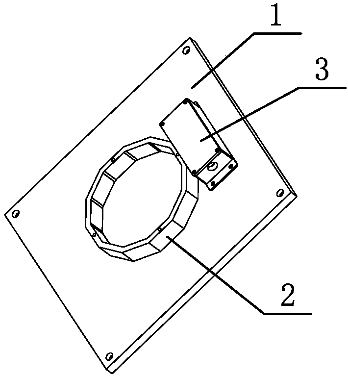
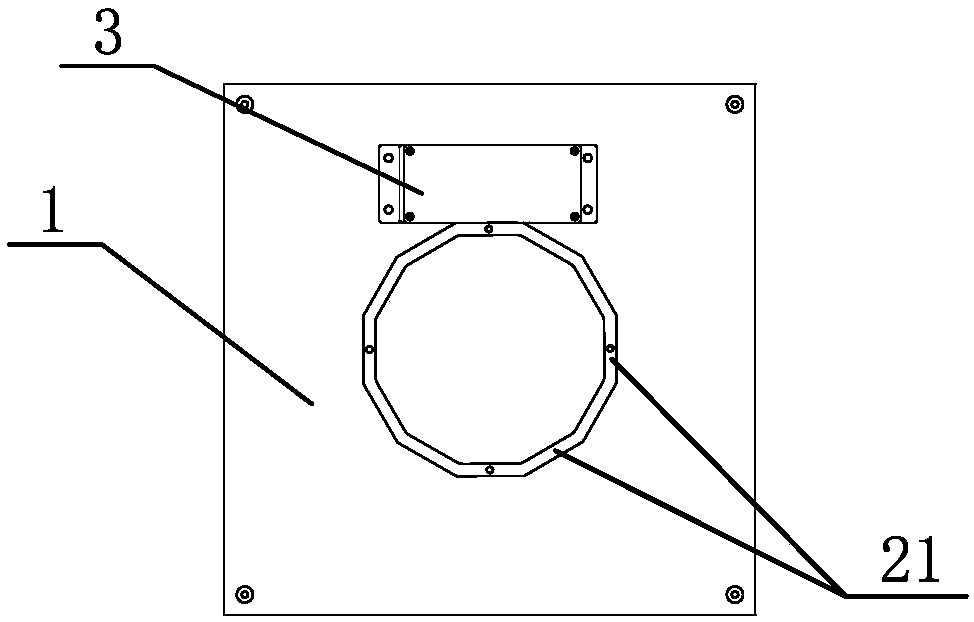
[0051] Such as figure 1 and figure 2 As shown, the test board of the calibration electronic compass of the present invention comprises a flat plate 1 and a side plate 2, the side plate 2 is fixed on the flat plate 1, and the side plate 2 is composed of n side walls 21 into a polygon, and the side walls 21 are perpendicular to the flat plate 1, The number n≧3 of side walls 21 . The polygon in the present invention is preferably a regular polygon, and n is preferably a multiple of 3, such as 12.

[0052] The invention uses the test board to calibrate the electronic compass with high precision, which can not only realize the high-precision calibration requirements of plane and two-dimensional, but also realize the high-precision calibration requirements of three-dimensional and full-space three-dimensional. Below, the electronic compass c...


PUM


Abstract

The invention discloses a test board for calibrating an electronic compass. The test board comprises a flat plate and a side plate fixed on the flat plate, the side plate is a polygon formed by combining n side walls, the side walls are perpendicular to the flat plate, and the number N of the side walls is equal to or more than 3. The electron compass to be calibrated is arranged on the flat plate, and is arranged close to the outer side of the side walls, the magnetic field value and the angle value of each point, measured by a magnetometer, are recorded, obtained data is processed through aninterpolation technology to obtain a corresponding relationship between the magnetic field and the angle, and a corresponding angle is solved according to the magnetic field value measured by the magnetometer through fusing the corresponding relationship with a roll angle and pitch angle which are measured by an accelerometer, so planar two-dimensional high-precision calibration requirements arerealized, and three-dimensional total-space stereo high-precision calibration requirements are also realized. The test board has the advantages of simple structure, convenience in operation, no need of a complicated test device, brining of great convenience for the use of a end user, and realization of self calibration of the electronic compass by the terminal user.

Description

technical field [0001] The invention relates to the technical field of navigation by using an electronic compass, in particular to a test board for calibrating an electronic compass and a calibrating method. Background technique [0002] In recent years, with the progress of society and the development of science and technology, the position and role of positioning and navigation in people's life have become more and more important. The rapid development of positioning and navigation not only affects people's life philosophy, but also profoundly changes people's way of life. Therefore, in different application scenarios, the calibration of positioning and navigation becomes more and more important. For example, in the military field, in order to improve the precision strike capability of weapons such as missiles, the significance and role of precise navigation are particularly prominent. At the same time, how to achieve precise guidance of missiles in the case of GPS signal...

Claims


Application Information

Patent Timeline
Patent Type & Authority Applications(China)
IPC IPC(8): G01C17/38
CPCG01C17/38
Inventor 时广轶肖亮王春波
Owner BEWIS TECH
Why Eureka
Try Eureka