Dye filling apparatus for hydraulics flow visualization test and test method

A flow display and filling device technology, which is applied in the field of hydraulic testing, can solve the problems of low dye injection efficiency, extended time for repeated injection of dye solution, and inability to inject dye solution at multiple points at the same time, so as to ensure the test effect , Improve the effect of injection efficiency

Active Publication Date: 2018-08-14
SICHUAN UNIV
View PDF9 Cites 4 Cited by
  • Summary
  • Abstract
  • Description
  • Claims
  • Application Information

AI Technical Summary

Problems solved by technology

[0004] Aiming at the deficiencies of the prior art, the object of the present invention is to propose a dye filling device and test method for hydraulic flow display tests to solve the problem of not being able to simultaneously inject dye liquor at multiple points, resulting in repeated injection of dye liquor. Problems with greatly extended time, low efficiency of dye injection

Method used


Image

  • Dye filling apparatus for hydraulics flow visualization test and test method
  • Dye filling apparatus for hydraulics flow visualization test and test method

Examples


Embodiment 1

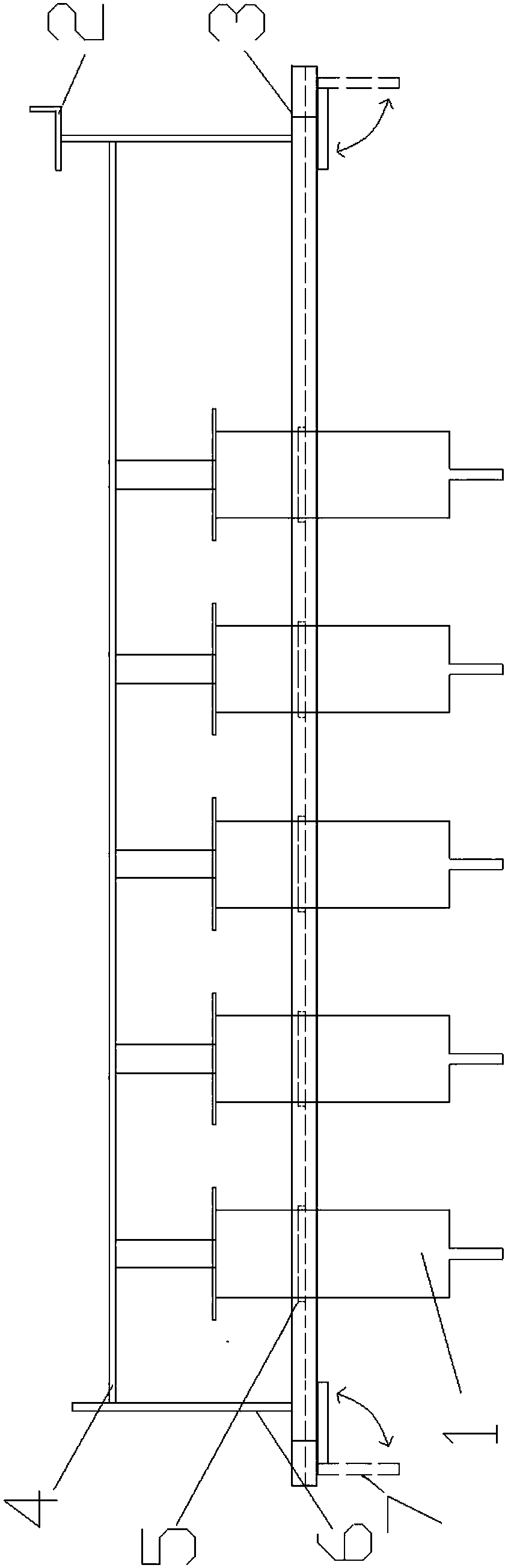
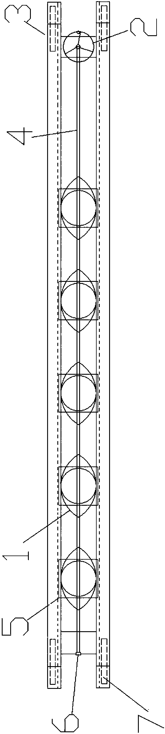
[0027] In this embodiment, as Figures 1 to 2 Said, a dye filling device for hydraulic flow display test, including a plurality of syringes 1, a lifting wheel 2, a telescopic rack 3, a pressure rod 4, a moving slider 5, an upper bracket 6, a lower bracket Bracket 7; the telescopic bent frame 3 includes two horizontally symmetrically arranged telescopic support transverse plates and a connecting block connecting both ends of the telescopic support transverse plate; the inner side of the telescopic support transverse plate has corresponding horizontal grooves; the moving The slider 5 is horizontally clamped on the barrel of the syringe syringe 1, and the two ends of the moving slider 5 are located in the groove; the connecting blocks at both ends of the telescopic bracket 3 are respectively provided with upper brackets 6 , and a lifting runner 2 is set on the upper bracket 6 at one end; the two ends of the pressure rod 4 that is fixedly connected to the piston handle of the syri...


PUM


Abstract

The invention discloses a dye filling apparatus for a hydraulics flow visualization test. The apparatus comprises a plurality of needle cylinder syringes, an elevating rotary wheel, a telescoping framed bent, a pressing rod, a mobile slide block, upper support racks and lower support racks, wherein the mobile slide block is horizontally connected on needle cylinders of the needle cylinder syringesin a clamped manner, two ends of the mobile slide block are positioned in a groove, the upper support racks are respectively arranged on connection blocks on two ends of the telescoping framed bent,the elevating rotary wheel is arranged on the upper support rack on one end, two ends of the pressing rod which is fixedly connected to piston handles of the needle cylinder syringes are respectivelyand movably connected to the upper support racks on the two ends, the elevating rotary wheel is connected with the pressing rod in a transmitting manner, and the invention also discloses a hydraulicsflow visualization test based on the filling apparatus. The beneficial effects of the dye filling apparatus and the test method are that dye liquor of a plurality of point locations can be injected atthe same time, the apparatus and the method are suitable for water flow visualization tests of test riverways of different specifications, and dye injection efficiency can be improved.

Description

technical field [0001] The invention relates to the field of hydraulic tests, in particular to a dye filling device and a test method for a hydraulic flow display test. Background technique [0002] The water flow display is the image display of the characteristics of the flow field. There are many ways to display the water flow, including the line cluster method, the coating method, the hydrogen bubble method, the optical method, and the color graphic method, but the tracing method is mainly used. The physical or chemical properties of the tracer material are used to display the characteristics of the flow field. At present, there are two commonly used methods: particle tracer method and color liquid tracer method. Among them, the particle tracing method is to display the flow field by placing a large number of floating or suspended particles evenly in the upstream of the display area, and obtaining a photographic image of a trace when the particles flow through the display...

Claims


Application Information

Patent Timeline
Patent Type & Authority Applications(China)
IPC IPC(8): G01M10/00
CPCG01M10/00
Inventor 王韦唐南波田忠许唯临刘善均张建民邓军曲景学余挺张法星
Owner SICHUAN UNIV
Why Eureka
Try Eureka