Centrifugal aeration stirring machine

A mixer and centrifugal technology, applied in the field of centrifugal aeration mixers, can solve the problems of bottom oxygenation, high noise, difficult installation and maintenance, etc., to achieve the effect of easy installation and maintenance, and reduce power loss

Inactive Publication Date: 2018-08-17
中节能国祯环保科技股份有限公司
View PDF3 Cites 1 Cited by
  • Summary
  • Abstract
  • Description
  • Claims
  • Application Information

AI Technical Summary

Problems solved by technology

The above-mentioned equipment has the following disadvantages: large power; difficult to install and repair on site; splashing sewage, loud noise; single performance, poor applicability; slow oxygenation, insufficient oxygenation at the bottom

Method used


Image

  • Centrifugal aeration stirring machine
  • Centrifugal aeration stirring machine

Examples


Embodiment Construction

[0012] The present invention will be further described below in conjunction with accompanying drawing:

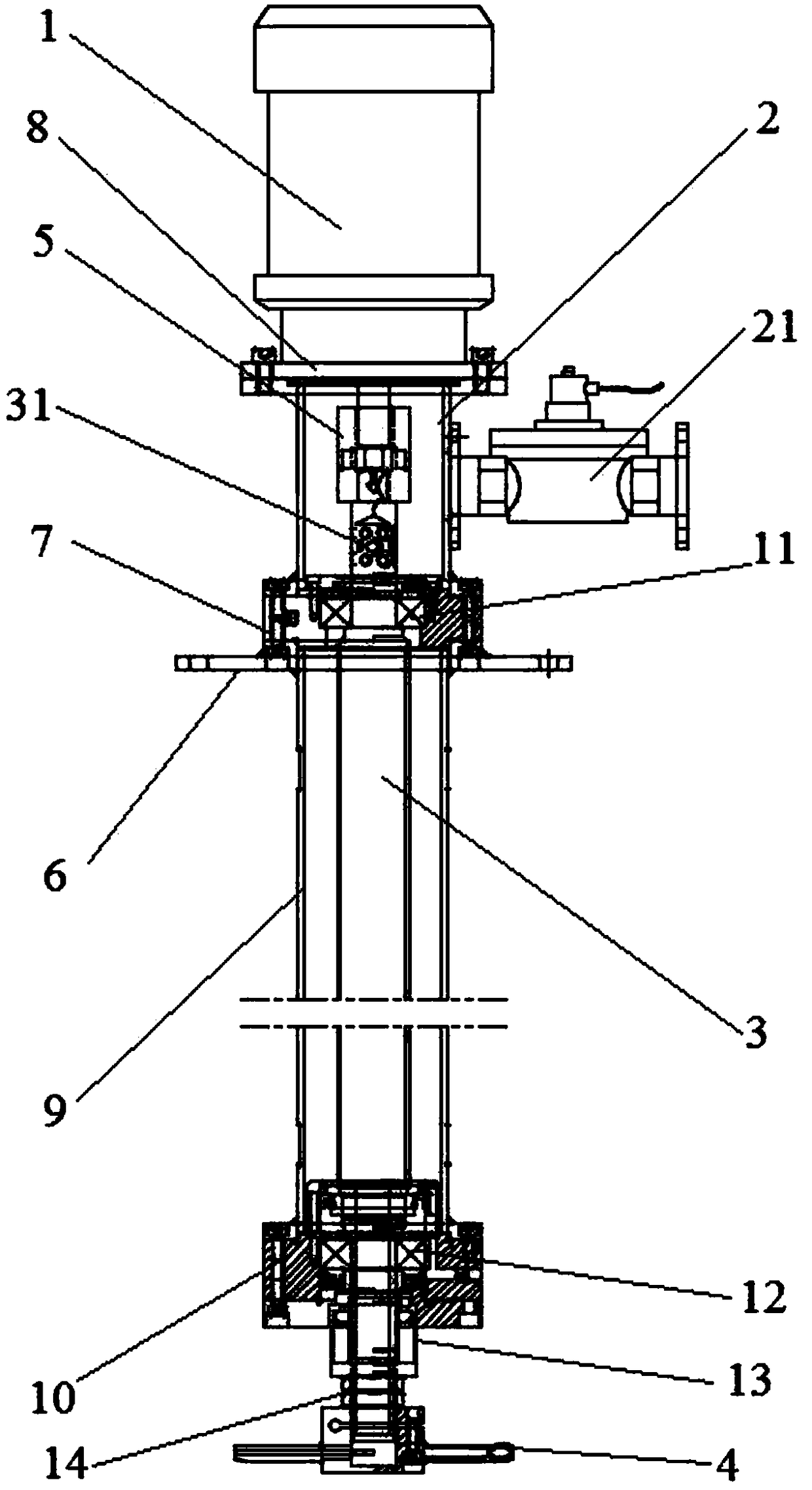
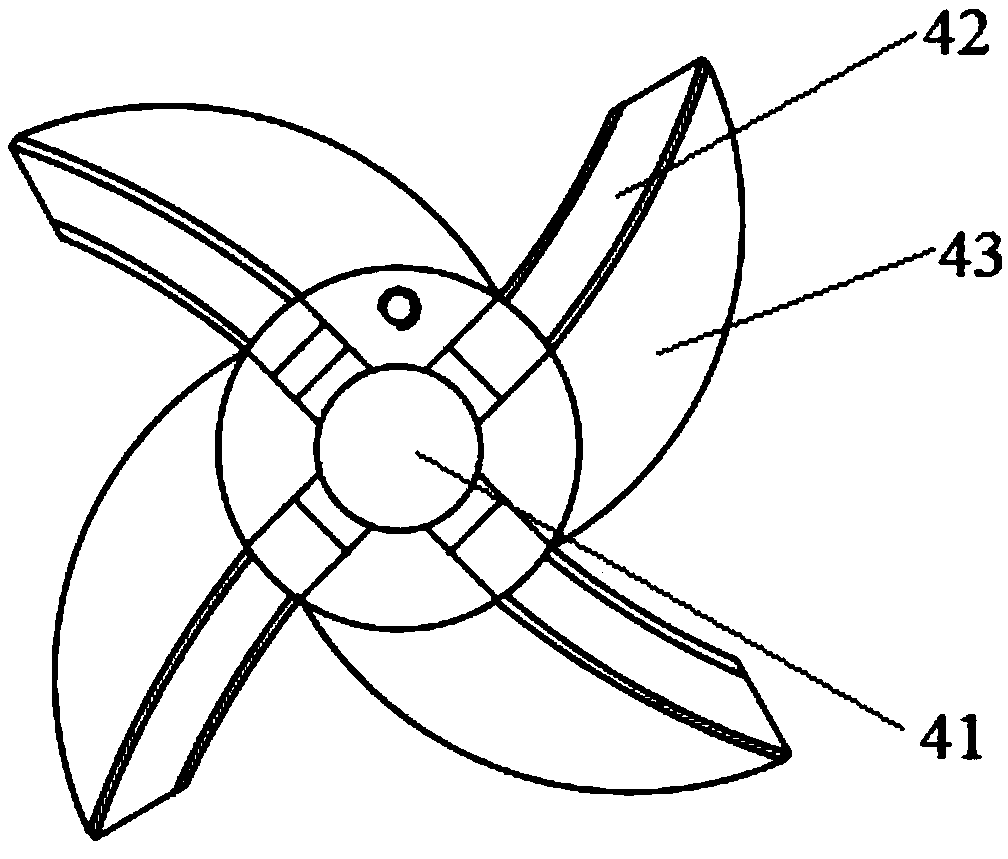
[0013] refer to figure 1 A centrifugal aeration mixer shown includes a motor 1 , an air intake chamber 2 , a main shaft 3 and an aeration impeller 4 .

[0014] One end of the main shaft 3 runs through the intake chamber 2 and is connected to the output shaft of the motor 1 through a coupling 5 , and the other end of the main shaft 3 is connected to the aeration impeller 4 .

[0015] As an embodiment of the present invention, the main shaft 3 is made of stainless steel, which has good anti-corrosion performance, and the main shaft 3 is connected to the impeller shaft 41 of the aeration impeller 4 through screw fit.

[0016] The main shaft 3 is a hollow structure, and the surface of the main shaft 3 in the air intake chamber 2 is provided with an air intake hole 31 communicating with the interior of the main shaft 3, and an air inlet is provided on the outer wall of the air ...


PUM


Abstract

The invention relates to a centrifugal aeration stirring machine which comprises a motor, an air inlet chamber, a hollow spindle and an aeration impeller. One end of the spindle penetrates the air inlet chamber and is connected with an output shaft of the motor through a coupler, the other end of the spindle is connected with the aeration impeller, at least one air inlet hole communicated with theinside of the spindle is formed in the surface of the spindle in the air inlet chamber, an air inlet is formed in the outer wall of the air inlet chamber, a connection and disconnection ball valve ismounted at the air inlet, the aeration impeller comprises an impeller shaft and a plurality of blades which are uniformly distributed around the impeller shaft, any blade comprises an arc-shaped centrifuge tube and a reinforcing rib connected with the corresponding centrifuge tube, an opening is formed in one end, far away from the impeller shaft, of each centrifuge tube, and the other end of each centrifuge tube is communicated with the inside of the spindle through an air channel in the impeller shaft. The stirring machine can adapt to different working environments and can be separately used for stirring and mixing, and stirring aeration can be achieved.

Description

technical field [0001] The invention relates to the technical field of sewage treatment and river channel management, in particular to a centrifugal aeration mixer. Background technique [0002] With the development of society, water resources are in short supply. In order to solve the problem of urban water shortage and improve the utilization rate of water, it is particularly important to carry out sewage treatment. At present, in the sewage treatment process, oxygen is generally provided to the sewage in the aerobic treatment link; when necessary, nitrogen and phosphorus removal treatment is required, no aeration is required, only stirring and mixing are required to prevent sludge deposition. Existing aeration equipment includes: inverted umbrella, rotating brush, rotating disc and jet aeration; push flow and mixing equipment are mainly flow pushers. Inverted umbrellas, rotating brushes, and rotating discs mainly use the rotating blades to agitate the water body, and the...

Claims


Application Information

Patent Timeline
Patent Type & Authority Applications(China)
IPC IPC(8): B01F7/00C02F7/00
CPCC02F7/00B01F27/112Y02W10/10
Inventor 何见光郑士良魏道春陈永林何枫林
Owner 中节能国祯环保科技股份有限公司
Why Eureka
Try Eureka